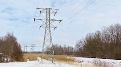
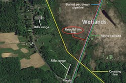
To increase reliability of the electrical grid just north of Syracuse, New York, U.S., National Grid needed to reconductor the 7-mile (11.3-km), 115-kV Clay-General Electric #14 line to increase its thermal rating. The reconductoring project would consist of replacing approximately 50 transmission structures. A mile (1.6 km) of the right-of-way (ROW) passed through the Hamlin Marsh, a swamp-covered lake bed with standing water and access restrictions. There also was a transmission line crossing, an adjacent buried petroleum pipeline and an active railroad very close to the ROW.
National Grid needed an environmentally sensitive, cost-effective foundation with low installation-induced vibration. It turned to Northline Utilities, which brought in Helical Pier Systems Inc. for the solution.
A Challenging ROW
The Hamlin Marsh is located in the town of Clay, northwest of North Syracuse in Onondaga County, New York. The marsh is more than 1,400 acres (567 hectares) in size and the majority of it is in wetland habitat. There is an actively managed wildlife management area inside the marsh with year-round public access and seasonal recreational activities including hunting. Mud Creek flows through the Hamlin Marsh wildlife management area and drops only about 2.4 ft (0.7 m) as it travels through the marsh, demonstrating the slow-draining, standing-water characteristics of the area.
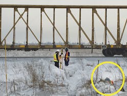
Since 1871, an active railway has bisected the marsh. In the 1920s, crews built a 115-kV transmission line only 50 ft (15 m) away from the track on a parallel alignment. A few years later, construction crews returned to the swamp to squeeze in a buried petroleum pipeline, which is still in use today, within 20 ft (6 m) of the transmission line. Two gun clubs with active rifle ranges are immediately adjacent to the ROW and the marsh. Careful communication and coordination would be necessary to prevent any incidents during construction.
Defining the Scope
To reinforce the line, National Grid determined the conductor would need to be upgraded to 795 kcmil (26/7) aluminum conductor, steel-reinforced (ACSR) Drake on double-circuit davit-arm steel monopoles, replacing the combination of double-circuit square-base lattice structures and flex towers supporting 4/0 copper and 477 ACSR conductor. Overall project construction was to begin in the second half of 2014, with completion scheduled for the following spring.
National Grid minimized the overall footprint within the environmentally sensitive marsh by reducing the total number of structures from 11 before the project to nine afterward. Also, both circuits on the double-circuit towers were reconductored through the marsh. As part of the environmental mitigation plan, wetland construction was scheduled to occur mid-winter. While this helped to reduce the environmental impact of the project, the foundations would need to be installed into frozen ground in sub-freezing weather.
Finding the Solution
Soil data could not be collected in the marsh because of the difficult access. Instead, one soil probe was driven to 40 ft (12 m) at the edge of the wetland. This confirmed adequate soils were at least 40 ft below this level. National Grid looked to Northline Utilities to develop a strong strategic approach to the challenging conditions. Northline researched and evaluated multiple foundation alternatives as an engineering procurement and construction (EPC) delivery method.
Traditional drilled-pier concrete foundations are vulnerable to sloughing and cave-ins during installation; prevention requires additional measures such as using casing to shore up the sides. These measures drive up costs and slow down the process of constructing a sound foundation. Vibratory steel caissons can work well for wetlands, but become costly at depths greater than 45 ft (14 m) and, because of the lack of sufficient geotechnical information, there was uncertainty as to how deep some of the foundations would need to be to perform as required. Additionally, some pipelines and railroad beds can be very sensitive to ground vibration.
The project team concluded foundations using helical piers would be the most cost-effective and environmentally friendly. Northline knew of other monopole foundation solutions designed and installed by Helical Pier Systems Inc. (HPS), so it contacted HPS to discuss the project’s foundation challenges. Drawing on extensive experience, HPS designed the various helical pier foundations the project needed.
Understanding Helical Pier Foundations
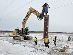
Helical piers, also known as screw piles, are generally fabricated by welding one to three helices onto a pipe shaft. A helix is similar to one thread on a typical screw. Just as with a screw, when a helical pier is rotated, it bites into the soil in which it is being screwed and advances the screw pile deeper into the ground. The fabricated pile can be screwed into the ground to an engineered depth and torque so it can bear load. The end of the pipe shaft can be fitted with a connection so additional pipe extensions can be attached as necessary to screw the pile deeper into the ground.
Helical piers can often be extended to reach depths greater than 100 ft (30.5 m) in search of soils strong enough to bear loads. The number and diameter of the helices can be increased or decreased to provide more or less load-bearing surface in the target soil, and both the thickness and diameter of the pipe shaft can be varied as needed to support the various forces encountered during installation and under structure load. As a pile is screwed into the ground, the soil is compacted to the side of the pile, eliminating the need to manage leftover soil, or spoils, that result from drilling.
Once the pile reaches the required depth and torque, the portion of the pipe sticking up above grade is cut to elevation, and a transition cap or assembly is field-welded to the pile. Finally, the above-grade structure or framework being constructed can be welded or bolted to the transition cap. Unlike concrete piles that require up to one month to reach their full load capabilities, helical pier foundations can immediately bear load so construction does not have to wait.
Engineering in Real Time
At the line crossing, the team discovered the actual ground elevation differed from the design survey data, causing the new line to encroach on the safe clearance of the crossing line above. To compensate, the Northline Utilities construction team designed and installed a coffer dam system to de-water and excavate the site to build the foundation 3 ft (0.9 m) below the grade of the swamp so it could achieve additional clearance from the existing overhead line. To protect the wetlands, water pumped out of the coffer dam was filtered, before being released into the surrounding swamp, to remove any impurities potentially introduced during construction.
To prevent accidental energization at the transmission line crossing, Northline Utilities developed a solution to isolate the circuits completely that were being reconductored by creating opens in each conductor. Furthermore, the circuits were bracket grounded on both sides of the crossing as an additional safety measure to prevent induced currents.
Because of the scarcity of geotechnical data, the team was not surprised that six of the nine foundations did not find sufficient load-bearing soils at the designed depths. To avoid any potential schedule impacts, pile extensions were quickly manufactured and shipped on-site to reach deeper into the ground for soils strong enough to bear the required loads. For one foundation, sufficient soils were not achieved until the piles reached a depth of 75 ft (23 m).
Conversely, but also not surprising, two of the foundations drove into soils so stiff the piers were unable to advance to the designed depth, hitting refusal 1 ft to 2 ft (0.3 m to 0.6 m) short. For both of these foundations, the real-time collaboration between HPS’s field crew and its engineers back in the office enabled calculations with immediate feedback to determine the foundations would work at their achieved depth. The field crew modified the helical piers in the field by cutting the remaining 1 ft to 2 ft off the tops of the piers.
HPS designed two specific foundation types for the project based on the unique characteristics of the location, the soils and the structure loadings: a tangent foundation and a dead-end foundation. Although each foundation pier was designed to an expected depth and torque, both foundations had the capability of extending any pier to the required depth to reach capacity, independent of every other pier in its foundation.
This capability, along with the significant flexibility in-field welding provides, gave the project team increased confidence these foundations could be adjusted on the fly to accommodate real-time variables encountered during installation to meet their required and critical performance parameters. This was essential because of the scarcity of geotechnical data; there was no way to know exactly how deep each pier would have to go to find sufficient soil capacity.
For straight-line tangent structures with low overturning moments, HPS designed a base plate that transitioned to a welded end cap attached to a very large (36-inch [0.9-m]-wide) helical pier. For additional support, smaller piers were installed around the perimeter and welded to the central pier. This design was quick to install even in cold winter conditions. Once the frozen soil layer was penetrated, it was easier to screw into the softer soils below.
For the two deadend structures, HPS designed an above-ground grillage strong enough to withstand the large overturning moments from those structures but portable enough to be field assembled. As an added advantage, no excavation was required with either foundation type, which was especially appealing considering the sensitive wetland environment.
Installing in Record-Setting Winter Conditions
Once the strategies were agreed to for overcoming the known and expected challenges of the ROW, the biggest hurdle remaining was the weather. The winter storms of 2014-2015 set records across the northeast U.S. Fortunately, helical piers are well suited for frozen ground and install very easily in most climate conditions, so foundation construction progressed smoothly.
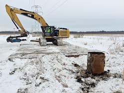
There were other challenges during construction. Because of the extreme cold, the steel for welding had to be preheated, and field welding tents had to be erected over the weld sites to keep snow off the work. Because of the frequent winter storms, snow removal from the environmental matting required almost continual operation. No sand or salt could be used because of the sensitive wetland environment.
In spite of the many challenges and obstacles for this project, the use of helical pier foundations provided numerous environmental advantages, flexibility and real-time adaptability, as well as significant speed of installation. The weather and sensitivity required while working in the wetlands significantly slowed construction speed, yet each foundation was completed and ready to erect the transmission structure within an average of three days. Surprise subsurface conditions in the field were quickly solved with an engineered response, ensuring the impacts on time and cost were minimized while maintaining excellent field safety performance.
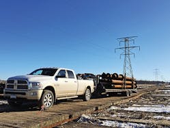
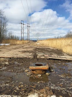
The nine structures were accessed by a 14-ft (4.3-m) matted road across approximately a mile of the Hamlin Marsh wetland. Materials had to be delivered by truck and gooseneck trailer to each site with minimal room to turn around. Accessing the last three structures on the far side of Mud Creek required a 200-ft (61-m) floating bridge over pontoons. Vibratory monitoring equipment was set up to ensure the buried lines and railway were not affected by construction vibration. The equipment confirmed no vibrations were generated from the helical foundation construction as a result of the low-impact, smoothly rotating screw pile during installation.
Throughout the ROW, the safe working clearance from the existing overhead lines required shorter than usual piles to be used. Because HPS designed, manufactured and installed the foundations, it was easy to coordinate the manufacture of shorter lengths and then field assemble them into the longer, required lengths during the installation process itself. This flexibility further confirmed the decision to use a helical pier foundation as vibratory caissons and anchor bolt cages are typically manufactured to a set length and cannot be easily lengthened or shortened in the field.
Planning Pays Off
Construction through the Hamlin Marsh was one of the more challenging aspects of the complex Clay-GE reconductoring project. This phase of the project required extensive planning and monitoring to ensure work was executed safely and without negative impact to the environmentally sensitive area. The efficient installation of the helical pier foundations in this phase of the project allowed crews adequate time to install the new structures and conductor, contributing to the successful completion of the overall project by the scheduled in-service date in the spring of 2015.
Acknowledgements
The author would like to thank Jim Palmer of Helical Pier Systems as well as Sean Sands and Joe Eisenhauer of Northline Utilities for their roles in creating this article.
Hilary Rotatori ([email protected]) holds a BSCE degree from Worcester Polytechnic Institute and a MS degree in engineering management from Northeastern University. She joined National Grid in 2010, and is currently in the transmission engineering department. She has worked on the engineering and design of various line refurbishment, new line and line reconductoring projects throughout New England and New York.
