By the end of 2014 a total power generation capacity of about 195 GW was installed in Germany. The capacity of wind power and of photovoltaic (PV) power each contributed, with 38 GW, close to 20 percent of the total. During sunny and windy weekends, up to 80 percent of electricity is generated from renewable resources. Germany’s target is to increase the share of renewables in the electricity mix from the existing value of 27 percent to 50 percent by 2030, and to 80 percent by 2050.
Due to Germany’s “Energiewende” (energy transition) decision, the country is quite advanced in the conversion from traditional power generation to renewables, but many other countries are following that path. Globally, China is leading the investments in renewable energy, where renewable power capacity now surpasses new fossil fuel and nuclear capacity. In the United States, a number of states have set mandatory targets for the percentage of renewable power generation, eg, the State of New York with 30 percent by 2015 and California with 33 percent by 2020. By the end of 2014, global installations of wind power exceeded 350 GW and PV power exceeded 180 GW.
Contrary to large centralized power plants, many of the renewable energy generators feed into the local distribution grid, either at low voltage (LV), which is mostly for PV, or at a medium-voltage (MV) level, which is mostly for wind power. Traditional distribution grids are designed to cope with the existing and expected future power flow of connected consumer loads, but were not designed for decentralized infeed, which can sometimes be much higher than the load power.
Especially in rural areas, generation of wind or PV power can quickly exceed the planned load power by a factor of 2 to 3 but can be as much as a factor of 10. Instead of a voltage drop along the electricity line from transformer to consumer, a voltage increase occurs near the producer. In many cases, the current-carrying capacity of the existing cable or overhead line is not a limiting value, and the line is not thermally limited. However, because generation is higher than the load power, the voltage rise can be very pronounced and exceed the allowed voltage band. This may result in the need to disconnect the generator.
There are different solutions to the voltage rise problem, like grid extension, installation of a voltage regulator, or use of reactive power. Which solution is the most economically efficient depends on the specific case.
European requirements for the grid voltage
The European standard EN 50160 [1] defines the requirements for voltage in public distribution networks. Under normal operating conditions the voltage at the customer site has to be within a range of ± 10 percent of the nominal voltage Un . In other regions, demands can be even more stringent. In the United States, for example, ANSI C84.1 [2] requires the utility to deliver power at the building’s service entrance within a range of ± 5 percent for LV and within – 2.5 percent to +5 percent for MV.
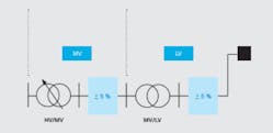
However, when considering today’s methods for the design of distribution grids in more detail, it becomes evident that the different voltage levels are firmly coupled and individual network levels do not have the full voltage bandwidth available. The last transformer able to adjust the voltage is the high-voltage HV/MV substation transformer. The total voltage bandwidth must therefore be distributed between the subsequent MV and LV networks. This results in a reduced voltage available for a voltage rise caused by local generation.
In ➔ 1 the ± 10 percent voltage bandwidth is equally distributed between MV and LV. In order to cope with all the different conditions at individual feeders, the grid design engineer needs to have defined fixed values. In this case ± 5 percent of the voltage bandwidth is attributed to each network level. It is also possible to asymmetrically distribute the voltage between the network levels. In Germany the LV grid typically gets only + 3 percent for voltage rise. This quite quickly limits the amount of power that can be fed into the LV grid.
The voltage drop in a typical copper cable with a 3 × 50 mm2 cross section caused by the current, corresponding to a transmission power of 120 kVA at 400 V, reaches 3 percent after 45 m.
Recalibrating the voltage
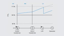
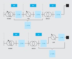
By using a line voltage regulator (LVR), the available voltage range is significantly increased and additional power can be fed into the grid without exceeding the allowed voltage range. An LVR is able to adjust or “recalibrate” the voltage level in the part of the grid subsequent to the LVR ➔ 2. In this example a generator is located at the end of an LV line. Without an LVR the voltage exceeds the allowed range. An LVR can be installed at any place in the grid. Depending on whether the installation is done in a single feeder line or at a bus having several feeders, only the voltage of the one feeder or of all feeders is regulated.
Voltage adjustments by the tap changer of the HV/MV transformer influence all MV and LV networks on its secondary side, although voltage drop and rise can be very different on individual feeders. The same is the case for regulated distribution transformers where voltage adjustments also influence the whole LV network. In the case of a feeder with a high amount of generation power, the LVR decouples it from the rest of the network. The reduction in voltage allows an increase in the available capacity while staying within the allowed voltage range ➔ 3.
Mode of operation of an LVR
An LVR creates an additional voltage, which overlays the existing line voltage Ul . This additional voltage is coupled in via a booster transformer and can be additive or subtractive. In ➔ 4 a variable voltage supply, fed by the line itself, creates a voltage URB, which is transmitted as UB into the line, resulting in the regulated voltage UR = UL +/- UB.
A transformer with an on-load tap changer (OLTC) is used as a variable voltage source. It allows the transformer to change the voltage stepwise between ± 10 percent. The OLTC has a linear configuration, uses mechanical switches and introduces resistors in the diverter. The switches of the OLTC allow up to 3 million mechanical operations without the need for any maintenance.
Dry-type transformers with RESIBLOC technology are used, making all components free of oil and eliminating any risk of fire or explosion. The RESIBLOC transformers are especially suitable for this application since they have high energy efficiency, offer high flexibility for providing any tap configuration, are mechanically very stable, are not sensitive to quick changes in load or temperature, and are qualified for temperatures down to – 60°C.
The ABB LVR does not create a galvanic separation in the regulated line and introduces a minimal additional impedance. The variable voltage supply circuit on the other hand is galvanically separated from the line. This feature makes the LVR equally suitable for use in grounded, impedance-grounded or insulated grids.
The LVR contains, in addition, disconnecting and/or earthing switches at the input and output sides, sensors for the measurement of voltage and current, as well as a bypass switch, allowing complete shunting of the LVR. The same functional principle is used for LV and MV.
An MV LVR installation in Germany
Westnetz is a subsidiary of RWE Germany and the major distribution system operator (DSO) for the western part of Germany. One of their 20 kV MV networks in the Eiffel region has over 200 generators connected (PV, biomass, small hydro) providing a total generation power of over 5 MW. The network currently extends over a length of 26 km and additional renewable power is to be connected in the coming years.
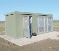
A grid study showed that neither active regulation of the HV/MV transformer nor broad use of regulated distribution transformers (totaling more than 60 MV/LV transformers) could solve the voltage rise problem. Westnetz therefore decided to use an MV LVR ➔ 5. It is installed at a distance of 10 km from the HV/MV transformer. This solution turned out to be substantially cheaper than an upgrade of the grid. Also, in this case, the existing cables have a higher current-carrying capability and are not a limiting factor [3]. The whole installation, including planning and issuing of authority permissions, was realized within a few months, ie, in a much shorter period than a grid extension would allow.
The LVR is able to adjust the voltage of transmitted power of up to 8 MVA by ± 10 percent. The voltage regulation is done in steps of 2 percent. The LVR has high short-circuit capability and voltage regulation occurs automatically. It is connected via RTU and GPRS communication to the grid control system. Westnetz has access at any time to measured values like voltage, current and power flow, as well as the status of the regulator. The LVR can also be operated in remote or local control mode.
Different modes for the control settings are available. It is possible to select a fixed voltage set-point value. The setpoint value can be modified via remote control, or can, for example, be based on a voltage measurement at a different location. The Westnetz LVR is operated by using a control curve, which is a function of the power flow and the flow direction on the MV line.
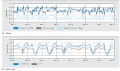
The graph in ➔ 6a shows the input (nonregulated) and output (regulated) voltage of the LVR and the voltage at the HV/MV substation (SS). The graph shows that during periods of high local power generation the LVR input voltage exceeds the substation voltage, while at night this reverses. The set-point voltage for the LVR is set to 20.5 kV. The regulated voltage remains well within a voltage control band set to ± 1.5 percent of this value. LVR input and SS voltage exceed 21 kV. Without LVR and with the maximum in-feed power of 5 MW, the voltage at the end of the network, 26 km away, would increase much more.
In ➔ 6b it can be seen that toward midday the power flow becomes negative, meaning that a power of up to 1.5 MW is fed from the MV network into the HV network. Overnight, typically between 5 p.m. and 9 a.m., the power flow reverses and up to 2 MW is supplied from the HV grid. March 15 seems to have been a rainy or very cloudy day since only a little power was locally generated.
An LV LVR installation in Switzerland
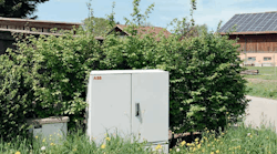
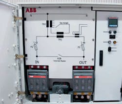
The roof of a farmhouse was to be covered with PV modules, providing a maximum power output of 134 kW. The farm is connected to the distribution transformer by a 250 m long 400 V cable. Several other customers are connected to the same transformer. A grid simulation carried out by ABB showed that the cable does not have a thermal limitation, but that the voltage rise will exceed the allowed range. An LV LVR was therefore installed in the middle, between the distribution transformer and the PV inverter ➔ 7 [4]. The LVR is installed in an LV cable distribution cabinet. Also, in this case, the installation of an LVR was much less expensive than adding additional cables.
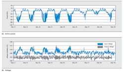
The LVR can regulate the voltage for a transmitted power of up to 250 kVA. The standard regulation range is ± 6 percent, or ± 8 percent, in voltage steps of 1.2 or 1.6 percent. Differences in the daily power profile seen in ➔ 8 represent the different weather conditions: While it was mostly sunny during the first five days, on day seven there was hardly any sun. Especially on days three, four and five the varying voltages indicate that there was broken cloud cover. During the night there was a load of 20 kW that was regularly connected.
Problem solved
Distribution grids are traditionally designed to cope with the expected power of existing and future loads. While the feed-in of renewable generation is increasing, the peak power of the generation can easily become a multiple of the peak load, bringing distribution grids to their limits. In many cases the limiting factor is not the transmission capability as such, but complying with the allowed voltage range.
An LVR can easily solve this problem. An LVR is able to automatically adjust the voltage of an LV or MV line, within a certain range, to a desired value and prevents the need for costly grid extensions.
The ABB LV LVR is installed in standard LV cable distribution cabinets. In most cases utilities do not need to get special permission to carry out such installations and LV LVR installations can therefore be realized very quickly. The MV LVR is installed in a concrete substation, completely mounted and tested, and only the MV cables need to be connected to the integrated MV switchgear. In both cases the LVR can easily be relocated and installed at another location if the situation in the grid is changing or further connection of generators requires a reinforcement of the grid.
Martin Carlen
ABB Power Products, Transformers
Zurich, Switzerland
[email protected]
Adam Slupinski
ABB Power Consulting
Mannheim, Germany
[email protected]
Frank Cornelius
ABB Power Products, Transformers
Brilon, Germany
[email protected]
-------------------------------
References
[1] Voltage characteristics of electricity supplied by public distribution networks, EN 50160:2010, 2010.
[2] Voltage ratings for electric power systems and equipment (60 Hz), ANSI C84.1-2011, 2011.
[3] M. Carlen et al., “Line voltage regulator for voltage adjustment in MV-grids,” presented at CIRED 2015, Lyon.
[4] F. Cornelius et al., “Erhöhung der Anschlusskapazitäten im Verteil- und Ortsnetz durch den Einsatz von Längsspannungsreglern,” in Von Smart Grids zu Smart Markets 2015 – Beiträge der ETG-Fachtagung, Kassel.
