The Federal Energy Regulatory Commission issued Order 867 on Jan. 23, 2020, approving Reliability Standard TPL-001-5 Transmission System Planning Performance Requirements. Reliability Standard TPL-001 was originally created to establish requirements for reliable operation of the bulk electric system (BES) during various system conditions and addresses a wide range of contingencies during abnormal operations.
TPL-001 contains several scenarios, from P0 to P7. Among these, P5 considers a multi-contingency scenario as “fault plus nonredundant component of a protection system failure to operate.” TPL-001-5 updated the analysis for redundancy of protection system relays to include all protection system components, including communication systems, dc supply and control circuitry. Even though it starts from a normal condition, the event considers a “delayed fault clearing due to the failure of a nonredundant component of a protection system.” In accordance with footnote 13 of TPL-001-5, a single-station dc supply associated with protective functions is considered a nonredundant component of a protection system.
Addressing TPL-001-5
Utilities can address the TPL-001-5 requirement in several ways for a single dc supply as part of a nonredundant component of the protection system. One method is to include a second dc supply for the protection system. However, this is significantly easier in concept than in application. Installing a second dc supply requires thoughtful planning, additional space requirements and rewiring of components to allow the primary and backup protection systems to be fed from different dc supplies. If the TPL-001-5 requirement is considered from the beginning of a substation’s design, these challenges can be overcome and provisions for proper primary and backup dc systems provided.
When considering retrofit or brownfield situations in existing substations, installation of a second dc system is difficult and oftentimes impossible to fully implement. This difficulty is usually because of space constraints in the existing substation control house and the significant effort required to rewire primary and backup protection systems to use the second dc system. Extensive planning and outage considerations are required, many of which are likely to be either cost prohibitive or ill-advised because of the compromised state the associated protection systems will be placed in during installation and
rewiring of the second dc system.
Low voltage can be sensed at different points, as electronic relays with this function are added across the substation. When the battery charger fails and the system is powered by a single dc source, voltage is constantly monitored by several relays and alarms are sent to the control center. However, the exception in the standard also calls for open-circuit monitoring.
Supply Monitoring
Baltimore Gas and Electric Co. (BGE) recently reviewed several alternatives for a dc supply open-circuit monitoring device. The most expensive solution was adding battery monitoring equipment attached to each individual cell. This solution would accomplish open-circuit monitoring and much more, but cost was a concern.
BGE then explored devices providing open-circuit monitoring only. A few devices are manufactured specifically to address open-circuit monitoring while other devices can be repurposed for it, such as meters. Many of these solutions would be intrusive to the system, requiring outages that would be costly and labor intensive.
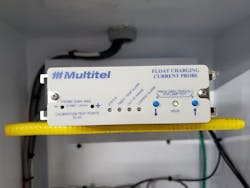
Ultimately, BGE chose to test Multitel’s Float Charging Current Probe (FCCP) device. The FCCP provides consistent measurement of float charging currents and programmable alarms that alert the control center of any possible loss of dc supply. Another reason BGE chose this device was because other utilities were planning on initiating similar pilot programs.
BGE Pilot
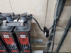
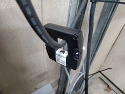
BGE started piloting this solution in August 2022 at a substation with only one dc supply. The FCCP device was installed, calibrated and tested within one day of fieldwork. It was installed on the wall of the substation close to the battery terminals, as BGE selected clamp-on CT cables about 10 ft (3 m) in length — although a 50-ft (15-m) option is also available. The CT was oriented to align with the current flow, and the FCCP device was programmed to trigger an alarm if no current flow was sensed for 30 minutes.
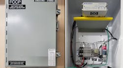
BGE engineering developed a standard design for a FCCP box that could be deployed at any facility requiring this open-circuit monitoring functionality. The box consisted of the following:
- Wall-mount-type enclosure that hols all the components
- Multitel FCCP sensor
- Power supply to step down from 125 Vdc supplied by the battery down to 24 Vdc for the device
- Struthers-Dunn relay with contacts rated at the same voltage level as the remote terminal unit
- Various terminal strips for easy connections
- Fuses to protect the device.
The FCCP operating voltage is between 18 Vdc to 60 Vdc. Therefore, the 125-Vdc to 24-Vdc power supply was added to the box to reduce the voltage level to be within the device input range. In addition, the FCCP output contacts are not rated for 125 Vdc, BGE’s common battery operating voltage. Therefore, the Struthers-Dunn relay was wired to the alarm output to convert the 24-Vdc signal to 125 Vdc, so it could be used for SCADA input.
The FCCP box provides all the components necessary for the design to work in a small space on the wall near the battery terminals using dc power from the existing 125-Vdc batteries at the substation. After the initial installation, an improvement to the design was engineered to add a light to the FCCP box indicating the power supply was in working order. As a result, technicians can now easily verify power is available to the unit without having to open the enclosure.
An additional pilot installation was done at another substation using alternating-current power supply to the FCCP device, to test a simpler installation method where dc supply may not be feasible. This solution provides BGE with the means to pilot both power supply solutions, offering the flexibility to use the best design for each substation as necessary.
Moving Forward
Although the TPL-001-5 standard does not require a redundant dc supply or monitoring to be installed at all locations (it just requires the use of this potential failure in analysis), BGE has decided to move forward with installation of open-circuit detection devices as a best practice at all its existing BES substations as well as new substations regardless of whether they are BES or not. For existing BES substations, the installation will occur in conjunction with preplanned relay and remote terminal unit upgrade projects over the next few years.
Jose Abi Karam Duran has worked at Baltimore Gas and Electric Co. for over five years and is currently in the transmission and substation engineering projects area as a senior engineer. Prior to that, Duran worked as a senior engineer in the distribution automation group, where he performed coordination studies for distribution automation reclosers and implemented sensor technology. He focuses on grid automation and intelligent devices. He studied electrical engineering at the Universidad de Carabobo in Venezuela and obtained his master’s degree in power and energy systems from New Jersey Institute of Technology in Newark, New Jersey.
Abbas Zaidi has worked at Baltimore Gas and Electric Co. for over four years and is currently in the transmission and susbstation cybersecurity area as a section engineer. Previously, Zaidi worked as a senior engineer in the system analysis and support group, where he was the subject matter expert of North American Electric Reliability Corporation PRC-005, PRC-025 and PRC-026 standards and maintained the day-to-day compliance program of relays in scope for these standards. He has previous experience at Exelon Nuclear, where he focused on the cable aging management program of the Exelon Nuclear fleet. He graduated with a BSEE degree with a minor in mathematics from the University of Connecticut and obtained his professional engineering license in electrical power engineering in 2016.
Benjamin Carstens has worked at Baltimore Gas and Electric (BGE) for the last eight years. He currently works as a section engineer in the transmission and substation regional projects engineering group. His previous experience in BGE’s transmission and substation engineering department includes work in the areas of system protection and control, North American Electric Reliability Corporation Critical Infrastructure Protection compliance and large substation projects. He holds a BSEE degree from the University of Maryland College Park and a master’s degree in power systems from Worcester Polytechnic Institute.
