The electric utility industry started out in an age of discovery and progressed to an era of innovation — not bad for an industry most critics call unadventurous. The first 20 or 30 years of the industry, the period of discovery, was really a time of invention. Think about it: Everything the industry needed to serve the customer had to be developed on the fly, and in real time, as customers realized the benefits of electric lights and motors.
Challenge does not seem to be a big enough word to describe what took place. It must have been an exhilarating time but stressful beyond belief. Imagine beginning a business with a few dozen customers and having it grow to thousands in what must have seemed like overnight.
Somewhere along the line, these early electric utilities saw an advantage in being interconnected, which brought a whole new set of problems to be identified and solved. As theory took form, the electrical grid began to emerge, and the apparatus known as switchgear played a crucial role in making it all possible. Switchgear is commonly defined as the combination of disconnect switches, circuit breakers, fuses, instrument transformers and the supporting structures used in the arrangement of this equipment. Some authorities also throw in the control and protection aspects for the apparatus, too, but its primary purpose is to control, protect and isolate substation circuits and equipment.
When switchgear first appeared on the scene, the early electrical apparatus was pretty clunky, requiring huge amounts of labor to keep them operational, but labor was plentiful and affordable. As the grid expanded, switchgear technology improved, becoming more efficient and cost-effective, but budgets got tighter and labor more costly.
Designed for Maintenance
One of the key pieces of equipment included under the switchgear designation is the circuit breaker, which has been the focus of research and development from day one. This device has impacted the basic configuration of the substation and arrangement of the equipment like no other apparatus. When the oil circuit breaker (OCB) was introduced, it was a big hit for utilities and held prominence for more than 60 years.
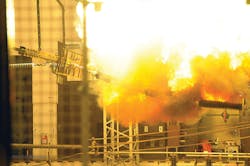
The OCB did a great job, and many are still in service today, but its complexity was an enormous problem requiring a great deal of maintenance just to keep it functioning. If it actually interrupted a fault, it had to be removed from service and inspected to determine if it could continue working.
Numerous outages were the norm rather than the exception because of the short maintenance cycles. How should a utility deal with a piece of equipment that is critical to the operation of the system but has to have long periods when it will not be available? Well, redundancy has to be built into the facilities where these devices are located. Accordingly, engineers developed several substation bus configurations, which were able to isolate the OCB for maintenance and still keep the power flowing.
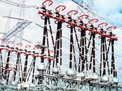
Utilities started with simple single-bus arrangements, which gave way to more complicated designs such as double-bus and ring-bus arrangements. Those were followed by the breaker-and-a-half design, double-breaker arrangement and the double-breaker/double-bus layout. Many variations of those designs were introduced, further improving system availability, but by adding layers of redundancy like this, things became complicated.
All of this additional equipment (such as breakers, disconnect switches and instrument transformers) added to the already staggering maintenance workload, which in turn increased the cost to operate the system. Substations grew in size and complexity, full of steel structures, bus work, equipment and transmission line terminations.
They were not only expensive to build and maintain, they became what many regulators and customers considered an industrial eyesore on the landscape. Those outside the industry wanted them kept as far away from population centers as possible. Zoning regulations became burdensome and, in high-value real estate areas, almost impossible to meet, but technology would help with this.
The Middle Ages
By the middle of the 20th century, customer demand was increasing at an incredible pace, and it was evident that a more dynamic grid was needed with increased capacities. The advancement in materials, new testing methods and improved manufacturing techniques set the stage to give some competition to mineral oil as an insulation medium. Timing is everything; the industry had pushed the OCB technology to its limits with voltage
(345 kV) ratings, and the system needed to be able to deliver more power and do it more efficiently.
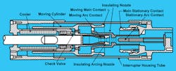
It was clear the industry needed to move away from oil’s limitations to be able to reach further into extra-high-voltage (above 230 kV to 800 kV) levels. The first technology to take us to 500 kV and beyond was the air-blast (contacts were blown apart by compressed air) circuit breaker technology, but air-blast breakers were complicated, requiring a lot of attention and maintenance. However, there was another technology beginning to attract attention: sulfur hexafluoride (SF6). SF6 offered the same high-voltage improvements as air-blast circuit breaker technology but with a mechanically simpler device.
Simply, Simplify, Simplify
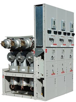
Interestingly, while all of this research and development activity was taking place at the higher-voltage levels, the medium-voltage (greater than 1 kV and less than 100 kV) portion of the grid was getting a makeover, too. Medium voltage needed more simplicity while increasing its power characteristics, and manufacturers were adapting new technologies here, also.
Air was a promising technology gaining attention with an arcing control device known as the arc chute. The arc chute technology was smaller and cleaner, and maintenance was simpler than oil. The chute was comprised of a number of metal plates set at right angles to the length of the arc chute with spacers between the plates, which looked like a subdivided chimney. It took advantage of the electromagnetic and thermal forces caused by the arc, using them to drive the arc up into the chute. This ingenious design split the arc into a series of smaller arcs, which increased the resistance to the arc and extracted heat from the arc. This was an effective method to extinguish the arc, but it had its limitations and problems.
The vacuum was another technology gaining importance in medium-voltage switchgear. The vacuum bottle held an interrupting device that was sealed for life, thus, no on-site maintenance. If there was a problem, the technician replaced the bad bottle with a new one and returned the old one to the manufacturer. It also offered an interrupter that could interrupt a fault without wearing out, thus, better contact life. The energy required for opening and tripping also was greatly reduced, which reduced the size of the battery and charger. This was a win-win for utilities. They reduced maintenance costs, and they had a device that was making installations simpler.
Vacuum breakers also brought superior electrical characteristics to the table such as having no restrike issues, which improved transient problems. It also was faster since the contacts did not have to move very far to interrupt the current, but it was not perfect, either. Like the higher-voltage levels, SF6 technology was coming to play in medium-voltage switchgear with positive results.
Insulation and More
As utilities became more familiar with SF6 technology’s strengths and benefits, its acceptance grew. SF6 gas has superior characteristics and arc-quenching abilities when it is compressed and blown across the circuit breakers contacts. Soon, a complete line of SF6 switchgear was offered for extra high-voltage levels. It did not take long for SF6 technology to become the technology of choice.
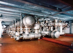
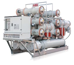
The fact that SF6 has excellent insulating properties at relatively low pressure did not go unnoticed, either. This property made it perfect for the development of a totally new piece of equipment: gas-insulated switchgear (GIS). The basic concept behind the GIS technology is the fact that SF6 gas is an ideal insulation medium for energized (phase-to-phase and phase-to-ground) switchgear components when used at moderate pressures.
These components (that is, high-voltage conductors, circuit breakers, disconnect switches, grounding switches, instrument transformers and surge arresters) are located inside a grounded metal enclosure in a SF6 environment. GIS became a reality when Brown Boveri & Cie, now ABB, developed the world’s first 110-kV GIS equipment. This
pioneering apparatus was placed in service at Sempersteig in Zürich, Switzerland, in 1967.
No Limits
Following closely on the heels of this groundbreaking GIS project, BBC went a step further. Why not take advantage of the GIS technology and make a substation that totally disappears? It installed the world’s first underground GIS substation at the city center in Zürich. It was rated 170 kV using GIS modules and became the first truly invisible substation located in the heart of a densely populated urban center. This underground GIS substation solved the issue of providing increased capacity in a congested cityscape where a visible high-voltage substation was not welcomed.
Designers realized that if GIS substations could be used underground, why not construct them inside hydroelectric dams or on top of, underneath or inside buildings? There was no limit. The GIS substation’s smaller footprint (one-third the size of air-insulated switchgear) and the reduction of electrical clearances allows engineers the flexibility of placing a substation where it is needed rather than where it can be permitted. It truly became out of sight, out of mind.
GIS improves the reliability and availability of the substation. It also reduces line losses by shortening the length of distribution lines when the GIS substation is located closer to the load center. GIS also shields the equipment from pollution, lightning strikes and those pesky animals determined to cause outages even at the cost of their own lives.
Extremely harsh environments such as deserts, high-altitude locations or offshore oil platforms are no longer a problem, either, now that the components are in a climate-controlled SF6 environment. GIS also has lower noise levels and lower electromagnetic emissions that allow for operation in residential areas or in sensitive industrial plants. Thinking outside the box is an old cliché, but in the case of GIS, engineers are thinking inside the box — the well-defined GIS enclosure.
Upping the Limits
For many years, the capacity of the grid was largely in balance with the demand, but that started changing after World War II. As the demand increased, the grid needed higher voltage levels, and GIS technology became more vital to meet that goal. In 1987, ABB introduced the world’s first 800-kV GIS substation in South Africa at Eskom’s Alpha substation. The 800-kV GIS facility was installed on Eskom’s 800-kV transmission system, proving the technology was maturing in a positive manner.
Less than 20 years later, the State Grid Corp. of China (SGCC) announced plans to move into the ultra high-voltage (above 800 kV) levels with the world’s first 1100-kV ac system. ABB together with Chinese switchgear manufacturer Xian Shiky developed a complete GIS components portfolio, including circuit breakers with closing resistors, disconnectors, grounding switches, current transformers, bus bars, bushings and insulators.
The SGCC ultra high-voltage ac demonstration project proved to be an excellent testing ground for the concept. The SGCC project consists of almost 600 km (373 miles) of high-voltage transmission lines and three substations — Jingmen, Nanjang and Jing Don Nan.
Going Boldly
For more than 130 years, the electric utility industry has been pushing the technological envelope for all it is worth. It has moved from the stone knives and bearskins (comparatively speaking) of the first electrical systems to today’s space-age smart grid.
The evolution of switchgear technology may have been painful at times, but it has always been exciting. There have been significant advancements in reducing the complexity of substations in terms of configurations and equipment while shrinking maintenance requirements.
In addition, the footprint of the switchgear has gotten much smaller. They also use less SF6 than earlier generations. At the same time, GIS and AIS characteristics (voltage and current ratings) have been increased to ultra high-voltage proportions, which are capable of moving gigawatts of power over
extremely long distances. Several years ago, the pundits of the industry had a favorite saying that Edison would be as at home in the typical substation as he would in one from his era. Balderdash, those pundits have not been in a substation lately.
Companies Mentioned
ABB www.abb.com
Eskom www.eskom.co.za
SGCC www.sgcc.com.cn
Xian Shiky www.xianelectric.com
Sidebar: Radiography of Switchgear Is a Technology Whose Time Has Arrived
In 1895, Wilhelm Conrad Roentgen discovered the imaging technology known as radiography (X-ray photography). It was a pretty radical concept when you stop to think about it. Roentgen discovered that electromagnetic radiation had the ability to pass through some materials and not others. He experimented with this and captured a film image of the bones in his wife’s hand, which freaked her out but won him the first Nobel Prize in physics in 1901. It also opened the door on a whole new way of looking at the world around us.
People realized that being able to see inside a piece of equipment without taking it apart made as much sense as seeing inside the body without cutting the body open. X-ray technology has been used by manufacturers for verification of factory-assembly processes, verification of welds on pressure tanks and piping, and a host of other procedures. What makes X-ray imaging technology so attractive isn’t so much the technology itself, but what the technology allows us to avoid.
Consider the old-school methods for inspecting switchgear. They are expensive, time-consuming and, frankly, not user-friendly. First of all, downtime has to be planned and coordinated far in advanced of the outage. Utilities are so interconnected that maintenance outages on the backbone transmission system affect everyone connected to it. There is also the issue of replacement parts. In addition, all the possible parts required (both known and unknown) must be on hand prior to the outage. No one wants to extend a maintenance outage because a replacement part isn’t available.
Before maintenance personnel even approach the equipment, there are many steps required. The circuit breaker must be disconnected from the circuit and isolated, which can be disruptive to the grid. There are also environmental issues associated with SF6 gas-filled switchgear. SF6 is a possible greenhouse gas that must be safely removed, stored and recycled. Once it is removed, the actual maintenance task of dismantling can take place. Opening the tank is labor-intensive and has the potential of risks from human errors. It is possible to introduce defects that were not present prior to opening, for example, parts could be lost, damaged or incorrectly fitted, or debris could enter the equipment and go unnoticed.
In addition, the circuit breaker is also exposed to external moisture, the introduction of possible leaks to the gas system and the increased risk of possible contamination to the inside of the breaker. Internal inspection is time-consuming, costly and not always effective. If you can reduce the number of times the circuit breaker’s tank is opened, it is better for the equipment, the personnel involved and the grid, which is why radiography is attracting attention.
Some recent projects have shown the benefits firsthand for X-ray imaging. One good example took place when Call Henry Inc. contacted ABB with some interesting questions and ideas. Call Henry Inc. is the high-voltage on-site support service contractor at the NASA Glenn Research Center in Cleveland, Ohio. Call Henry Inc. talked to ABB on behalf of the research facility regarding the health of the center’s 26 ABB-type 38PM40-20 SF6 gas power circuit breakers. The center leads NASA’s research and development in the area of aero-propulsion and specializes in turbo-machinery, power, propulsion and communications. It also leads research in the microgravity science disciplines of fluid physics, combustion science and the field of microgravity acceleration measurement.
NASA Glenn and Call Henry reviewed the maintenance data and determined that many of the research center’s circuit breakers were 10 to 14 years old, with one breaker having completed more than 2,700 operations during its lifetime. It was apparent that these breakers were working hard and were due for an internal inspection. The big problem was the time required to take the breakers out of service to inspect them and service them. ABB proposed using X-ray imagining to reduce outage time and maintenance. This approach has been successful in previous projects where time has been a critical issue, and radiography seemed like a natural approach given the high-tech nature of NASA and its research centers.
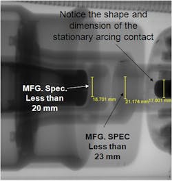
Radiography imagining is a straightforward process. A group of technicians specializing in the process take the images. OEM (original equipment manufacturer) experts then review the images, checking dimensions and tolerances against original component and assembly drawings. Radiography eliminates the need to breech the sealing system of the equipment being diagnosed, increasing equipment reliability and making infiltration of external contaminates a non-issue.
The outcome of X-ray inspection of NASA Glenn Research Center’s 26 circuit breakers resulted in one breaker requiring entry to remediate a hardware problem. Seven of the breakers required minor maintenance that did not require internal work. Nineteen breakers were entirely spared entry and intrusive maintenance. The team estimated that a huge amount of labor-intensive internal inspections were saved as a result of performing the external diagnostic testing with X-ray imaging.
Radiography equipment is becoming an important tool for utilities interested in reducing maintenance costs and time required to perform that maintenance on power circuit breakers. If you can reduce the number of times the circuit breaker’s tank is opened, personnel are safer, and the environment is protected. When you stop to think about the number of power circuit breakers in service throughout the world, this new maintenance tool truly has the potential of changing our industry for the better.

