The display screen on the FLIR T400 unexpectedly shifts from a pattern of violet hues to bright white; the infrared camera is aimed at a jumper that runs from a tie switch to the 69-kV bus. The jumper is 1,000-kcmil copper and part of a 35-year-old wire bus infrastructure located in a 60-year-old substation of Central Lincoln People’s Utility District.
The jumper is carrying double its usual load and nearing its capacity, as the only other 69-kV feed at this substation has been de-energized. The temperature of the jumper, while very high, remained fairly steady, so the decision was made to continue the process of swinging the de-energized 69-kV line into its new position. More than half of the utility’s 38,500 customers and its largest industrial customer are receiving their power through the closely monitored jumper.
The Lower Olalla substation, located 7 miles (11 km) east of the Pacific Ocean on Oregon’s central coast, is a 69-kV switching station interconnecting five transmission lines and serving one local power transformer. It is the only power source for two-thirds of Central Lincoln’s load, serving 15 area substations, thousands of customers and a large industrial plant. The substation sits in both a 100-year floodplain and tsunami impact area with a mere 1,000-A capacity, limited
operational flexibility and aging infrastructure, giving cause for safety and reliability concerns. Replacing Central Lincoln’s most critical substation was essential.
Collaboration, Cooperation and Coordination
In spite of its efficient staff size of 130, Central Lincoln has developed the capability for the design and construction of its own substations. The rebuilding of the Lower Olalla substation was the largest project in the utility’s 70-year history and involved more than half of the employees, including civil and electrical engineers, a transmission specialist, a substation crew, operations crews, communications and network specialists, relay technicians, and procurement and warehouse staff.
Planning for the rebuild of the Lower Olalla substation began more than 10 years ago. Early project complexities included the acquisition of land, the close proximity of wetlands and nearby flooding hazards. After land acquisition, mitigation and hazard evaluation, planning began with the preparation of the substation one-line diagram. This was a collaborative process involving design engineers, operations personnel and substation craftsmen. The process also included consideration of land and water constraints, safety, operational flexibility, ongoing maintenance requirements and the necessity of physically isolating the energized portion of the substation from the areas of construction. On completion of the one-line diagram, phased build plans were detailed, all National Electrical Safety Code clearances were confirmed, and a load-flow analysis was conducted to identify and mitigate issues that might halt or hamper the construction process.
The final substation design included a larger control building, eight 69-kV SF6 breakers, a 2,000-A main and auxiliary bus with a bus differential, a capacitor bank and transmission distance relaying using fiber-optic cable. The five-phase, six-month plan included keeping the original substation energized, an outage strategy for the five transmission lines interconnected with the substation and raising the substation from 10 ft (3 m) above the mean sea level (MSL) to a final elevation of 16 ft (4.9 m) above the MSL.
Material Procurement
Using computer-aided design (CAD) software, the substation one-line diagram was converted into a 3-D model; a parts list was generated along with design specifications for the steel manufacturers and foundation details for local contractors.
In all, the new substation would have more than 25,000 pieces of fabricated steel, bolts, nuts and washers. The steel structures alone would weigh 132,000 lb (59,874 kg), an construction components would include 2,800 ft (853 m) of 3-inch (7.6-cm) aluminum bus, 520 bus compression fittings, 4,000 lb (1,814 kg) of copper for the ground grid and 19,000 ft (5,791 m) of control cable. In addition, three steel transmission deadend structures would be required outside the substation.
With lead times exceeding six months for the manufacturers and suppliers, it was critical for material quantities and design details to be absolutely perfect.
Construction
Over 18,000 cu yd (13,762 cu m) of fill and rock were added in layers to raise and level the substation. After the first layer was compacted, forms for the steel support footings were constructed and poured by a local contractor. A second layer of fill was added to bring the elevation up to the ground grid installed by the substation crew. Substation rock was the final layer added to bring the substation up to final grade. Ultimately, more than 1,600 truckloads of material were brought into the substation.
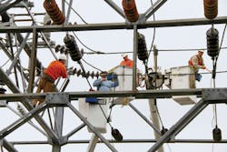
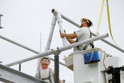
To ensure an efficient installation process, the substation crew, in spite of limited space within the secure area, carefully staged the steel and hardware. The steel structures were constructed quickly and provided the first sign of an emerging substation. Installation of disconnect switches, insulators, bus supports and the substation bus followed. Central Lincoln uses DMC Power compression bus fittings, which reduce the installation time by three weeks over the traditional bus welding. The utility has experienced very high reliability with the compression-bus-fittings approach, and this approach has proven effective in a coastal environment of high winds, heavy rain and corrosive sea salt air.
After the bus construction, the installation of circuit breakers and external control panels followed. Because of the coastal environment of its territory, Central Lincoln requires all of the external metals on devices installed in its substations to be made from hot-dipped galvanized steel, 304L stainless steel or 5000-6000 marine-grade aluminum, including circuit breakers and switches. In the case of the Lower Olalla substation, 304L stainless steel was used on the 69-kV SF6 breakers and all control cabinets are considered weather tight with heaters, thermostats and vents to prevent condensation.
After installing the breakers, the substation crew moved into the control house to complete the panel wiring. Months earlier, the crew had assembled the panels, installed relays and performed some preliminary wiring so only the final panel and substation device wiring were left. Central Lincoln’s meter and relay technicians performed the final panel relay testing with the substation crew.
New elements in the control house included three 69-kV panels with supervisory control and data acquisition (SCADA) bitronic meters; SEL-311L and SEL-411L line differential relays; an auxiliary panel with SEL-311C push-button relay; two main position panels for the Bonneville Power Administration with PowerLogic ION7650 meters and SEL-2100 logic processor for a transfer trip scheme; a capacitor bank panel with three Cooper relays; a bus differential panel with two SEL-487B bus differential relays; a panel with SEL-3530 real-time automation controller (RTAC) plus two SEL-2440 discrete programmable automation controllers; and a 400-Ahr battery bank and charger to provide backup power. All of the devices communicate to a SEL-3530 RTAC data concentrator using DNP 3.0 or SEL serial protocol.
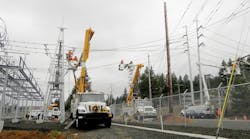
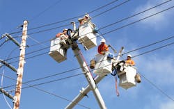
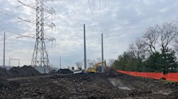
Another major element of the project included the installation of five transmission structures and the rerouting of the transmission lines to the new substation terminals. Using Power Line Systems’ PLS-CADD, and with consideration for the substation’s 7-mile (11.3-km) inland location, the three steel and two wood structures were designed to withstand 107-mph (172-kmph) winds and insulated to a 138-kV level to protect against marine air contamination. Central Lincoln operations crews installed the transmission structures and rerouted the transmission lines efficiently, on time and safely. At times, nearly all Central Lincoln’s high lift trucks, with buckets elevated, were in use on this project.
System Protection and SCADA
Twenty years ago, Central Lincoln installed fiber-optic cable throughout its service territory in an effort to ensure a reliable communications system. Today, redundant fiber-optic loops exist throughout most of the utility’s service territory and a skilled communications crew maintains fiber, microwave, radio, telephone and advanced metering infrastructure communications systems. The utility was able to leverage its strong communications network and implement a new SCADA system throughout the district as part its overall Smart Grid Investment Grant project.
SCADA architectural and equipment upgrades at the Lower Olalla substation involved changing out intelligent electronic devices (IEDs) as well as communications protocols to enhance safety, system protection, situational awareness and cyber security. In addition, Central Lincoln upgraded its enterprise SCADA human-machine interface (HMI) to an electric-utility-specific SCADA-HMI, which minimized the number of custom functions and features, thereby reducing operating and maintenance costs, and improving serviceability and maintainability of the HMI.
The new Survalent SCADA-HMI solution allowed all database and graphics modifications to be performed on the application without negatively affecting reliability and the availability to SCADA users. Also, engineers worked with operations personnel to design IED templates into the SCADA screen, which allows dispatchers to scroll through relays as if they were in the control house.
The Lower Olalla substation protection system includes line differential, distance relaying, overcurrent, bus differential and capacitor bank protections, as well as a transfer trip scheme to shut down the neighboring industrial cogeneration plant. The line protection system uses the utility’s fiber network to communicate with remote line-end relays, which provide line differential protection. These multifunction line relays also provide distance and overcurrent protection.
The 69-kV bus was designed to be reconfigured through two motor-operated switches; therefore, a bus differential protection system was implemented that could likewise be reconfigured. Inputs from the switches allow the relay configuration to occur automatically whenever the switch states are altered. The capacitor bank protection monitors capacitor string current and impedance, and trips when thresholds are reached. The protection logic and settings were tested prior to installation and final testing was completed on site.
Future Value
The 70-plus employees involved in the construction of the Lower Olalla substation brought their individual talents and skills together for a project that met all expectations. The substation project was completed safely, within a tight construction schedule and without outages. Over time, the Lower Olalla substation should prove to be a great value for the customers of Central Lincoln.
Acknowledgements
The author wishes to thank the following contributors: Steve Alexanderson, senior systems electrical engineer for Central Lincoln People’s Utility District, designed the protection schemes for this substation project; Dale Dawson, senior systems civil engineer for Central Lincoln, was the principal design engineer and project manager; Shamus Gamache, senior systems electrical engineer for Central Lincoln, was in charge of major equipment procurement, substation wiring design and SCADA; Joseph Monsanto, senior systems electrical engineer for Central Lincoln, ensured a successful SCADA integration; Erik Halverson, transmission specialist for Central Lincoln, designed and managed the installation of the transmission structures; and Gail Malcolm, program analyst for Central Lincoln’s smart grid project, served as the initial editor.
Bruce J. Lovelin ([email protected]) is the chief engineer and systems engineering manager for Central Lincoln People’s Utility District. He is in charge of the utility’s substation, transmission and smart grid projects, and is a professional engineer.
Companies mentioned:
Cooper| www.cooperindustries.com
DMC Power| www.dmcpower.com
FLIR| www.flir.com
Power Line Systems| www.powline.com
PowerLogic| www.powerlogic.com
SEL| www.selinc.com
Survalent| www.survalent.com
