Gounding systems installed by transmission and distribution utilities can be difficult to test as they are often extensive and can have very low impedance. The traditional portable ground testing equipment available is designed primarily for relatively small systems and, in many cases, is not able to measure very low resistance. In particular, it cannot test reliably or easily for touch, step or transferred voltages. Grounding systems must be able to perform correctly during the infrequent but serious power-system ground-fault events. Inadequate grounding systems can result in hazardous voltages arising under fault conditions.
To comply with statutory and regulatory requirements, utility grounding systems for existing and new substations should be subjected to testing when installed and again every few years under a maintenance regime. Testing is required to ensure that during a ground fault, the general public and field staff are not exposed to any hazards. Further, telecommunications equipment should not get damaged and voltage hazards should not be transferred onto other facilities or services such as fences, gas pipelines or water pipelines. The magnitude of the ground potential rise (GPR) and the associated voltage hazards are directly linked to the layout, fault currents and impedance of an overall grounding system.
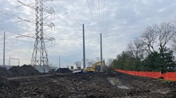
Westpower Ltd., a distribution utility on the West Coast of New Zealand, was faced with the need to undertake grounding compliance testing at six 66-kV and 33-kV substations. It needed to determine the overall grid system impedance and ground fault potentials on security fencing, high-voltage plants, water pipes and metalwork in nearby buildings, as well as to identify the GPR contours to ensure that no dwellings or telecommunications were within the “hot zone,” where GPR is above the allowable threshold. In some cases, existing ground grids can be modeled using appropriate software. However, experience has shown it is almost always cost beneficial to also test the ground grid instead of attempting just to model the grounding system.
Few practical methods exist for comprehensively testing such grounding systems. However, Westpower was well aware of the Mitton Instruments ground grid off-frequency injection test equipment, which had a proven track record of use throughout New Zealand and Australia. For this ground testing project, Westpower staff used the Mitton Instruments ground grid injection test equipment with the assistance of staff from both Westpower and Mitton Instruments.
Ground Testing Equipment
The objective of the test program was to produce, for each substation site, a comprehensive test report that included recommendations for mitigation or ground grid modifications to eliminate any identified hazards. The testing also provided a footprint for future reference.
IEEE Standard 81.2-2012, Guide for Measurement of Impedance and Safety Characteristics of Large, Extended or Interconnected Grounding Systems, includes a background on ground testing and the various test methods that can be applied. The difficulty in ground grid injection testing is to implement a method that does not require a substantial power-system outage to enable the injection of relatively high test currents needed to overcome background electrical noise. One method is to use off-frequency low current injection, whereby a signal is injected into the ground system at a frequency very close to the system frequency. Tuned voltmeters are then used to detect the resulting voltage signals on the grounding system.
The method and equipment are generally suitable for both large and small substations and switchyards (for example, 11 kV to 500 kV) and power stations.
Mitton Instruments has developed specialized equipment to undertake these tests that replicate, on a small scale, the effects of a ground fault on the grounding system. The LCI2000 portable low current injector operates at 58 Hz, and the associated TVM1000 voltmeter is tuned to 58 Hz, with exceptional rejection of the 50-Hz residual noise and any associated harmonics. The LCI2000 operates as a current source and this means no special power-transfer-matching transformers are required.
By using this method, only the test signal is measured, and any fundamental, harmonic or other noise on the grounding system or noise induced in the test cables is rejected. In addition, the unique signature of the 58-Hz signal may be identified easily at significant distances from the substation under test, such as on farm fences, low-voltage grounding systems, substation or power station infrastructure, and third-party equipment such as gas or water pipelines.
Off-frequency injection, together with sensitive measuring equipment, allows identification of the unique and often relatively low signal levels against the much higher background noise levels. The grounding system parameters can be measured without de-energizing the substation. The same test equipment is available for 60-Hz systems where the injection current and tuned voltmeters are set at 52 Hz.
Both new and existing switchyard grounding grids have been tested using this instrumentation. The results confirmed both the ground grid design and the effectiveness of the test equipment. Computer models and test results show close correlation, including predicted touch voltages in and around the sites. However, as mentioned previously, the main benefit of injection testing is to determine the ground grid performance since, in the majority of cases, the actual performance will differ from the design because of the many variables associated with grid design and practical installation.

Ground Testing Method
The injection circuit can comprise either a distribution or transmission line, or an independent cable. The latter is preferred if a suitable cable route is available as it enables independent grid testing and is simpler to organize. For best results, the inspection point should be located at a distance of at least five times the diameter of the ground grid under test.
The LCI2000 injector is capable of injecting up to 10 A rms, a value that will remain constant irrespective of any change in ground resistance as a result of remote test ground rod heating.
If a de-energized overhead line is used, induced currents should be considered first where the line is in parallel with an energized circuit. The equipment can operate with several amps of induced system current. The out-of-service line should be well grounded at the remote end or at a position along the line.
In the substation grounding tests conducted for Westpower, an independent cable was used to inject the test current into the grounding system. Ideally, the remote end of the injection circuit should be the lowest possible resistance; this can be achieved by locating the remote ground rods in a swampy area, pond or creek, or by saturating the surrounding soil with a mild saltwater solution.


Impedance Measurements
To determine the grounding system impedance, the voltage rise of the ground grid is measured with respect to the ground grids under test. The GPR is recorded using the TVM1000 tuned voltmeter. Readings are taken at intervals that gradually increase from the grounding system until the value of GPR is constant (that is, the position of remote ground has been reached). In some cases, it may be possible to use a local telecommunications circuit to provide a second remote ground reference.
It is preferred to take the GPR readings on a route approximately 90 degrees (perpendicular) to the route of the injection current to minimize errors caused by any induced voltage created by the injection current. This is particularly significant when the grounding system impedance is below 0.5 Ω.

The maximum test GPR divided by the test current yields the impedance of the grounding system. For very low impedance grids, which can be quite inductive, it can be useful to measure the phase angle between the voltage and current to determine the impedance angle. This can be done using the TVM1000P, which includes a phase-angle measurement option.

Touch and Step Voltages
The open-circuit touch voltages at each substation were determined by using the TVM1000 and a metal plate to measure the voltage between the metallic item under test and the ground surface at a 1-m (3.3-ft) distance. The prospective voltage is independent of the ground surface treatment or soil resistivity (and is the same voltage the ground grid design software programs calculate).
The touch voltage measurement is repeated with a 1,000-Ω resistor across the voltmeter input to provide an indication of the actual touch voltage that would arise across a person’s body. With the resistor loading the voltage source, the touch voltage is reduced depending on the surface contact resistance with the metal plate. For example, a prospective test touch voltage reading of 500 mV on a crushed rock surface may reduce to 20 mV when loaded with the resistor. These results confirm the beneficial effect of using crushed rock as a surface layer in substation compounds.
On natural soil, a similar test may only reduce the 500 mV to 400 mV, indicating low soil surface resistivity. The TVM1000 includes a switchable 1,000-Ω resistor to facilitate the procedure. Step voltages are measured in a similar way. The results of the touch and step voltages tests are scaled up by the ratio of maximum ground fault current to test current. The ground grid characteristics under actual fault conditions then can be compared with the acceptable touch and step voltage limits in IEEE 80 or similar standards or regulations.
Impact of GPR on Telecommunications Equipment
The GPR arising from power-system fault current is of particular interest to telecommunications companies. The rise in ground potential can cause insulation failure and other damage to telecommunications equipment, and can also be a hazard to staff working in the vicinity. The GPR traverse measurements can be used to assess the severity of the GPR arising as a result of a power-system grounding fault.
By replotting the graph with respect to remote ground, the actual ground surface GPR can be determined by using the ratio of real fault current to test current. This provides the GPR contour locations, for example the 430-V contour that may be of significant interest to telecommunications companies. In this example, the GPR contour of 430 V was located at approximately 20 m (66 ft) from the edge of the ground grid.

Current Splits
The current injection method enables the effect of additional ground paths provided by cable screens and overhead ground wires to be determined. The test current can be measured in these conductors using a flexible current transformer and TVM1000 or TVM1000P. The current transformer can be placed directly around power cables to measure the test current in the cable screen/sheath.
Where possible, the phase angle of the current split also should be recorded, particularly for cable screens, which can be quite inductive. Proportions of test currents can be detected in almost any conductor such as buried services, low-voltage power supply cables, telecommunications cable and gas pipelines, provided the current transformer loop is large enough to encompass the service.
Compliance Achieved
The off-frequency test equipment enabled the grounding systems of all Westpower’s substations to be tested effectively. Where hazardous touch and transferred voltages were identified, the engineers were able to propose suitable forms of mitigation such as additional buried conductor for gradient control, crushed rock to increase contact resistance, and the electrical isolation of fence sections. The GPR contours were identified and this ensured that no telecommunications systems would be compromised. Overall, the use of this test equipment and methods enabled Westpower to demonstrate compliance with statutory regulations and health and safety requirements.
Acknowledgement
The author wishes to acknowledge the assistance and technical support provided by Tony Mitton of Mitton Instruments in the preparation of this article.
Rodger Griffiths ([email protected]) has held various engineering positions with Westpower Ltd., a distribution utility on the West Coast of New Zealand’s South Island, and now works as an asset manager for ElectroNet Services Ltd., a Westpower subsidiary. He is responsible for the management and performance of all Westpower’s assets, including transmission equipment up to 110 kV and the ongoing development and rollout of asset management strategies. Most recently, Griffiths served on the Electricity Engineer’s Association National Working Party, developing the “Guide to Power System Earthing Practice,” a document developed to assist with compliance with the New Zealand electricity safety legislation.
Companies mentioned:
IEEE | www.ieee.org
Mitton Instruments | www.mittoninstruments.com
Westpower Ltd. | www.westpower.co.nz