On April 4, 2010, an earthquake with a magnitude of 7.2 occurred in northern Mexico and was felt as far away as Los Angeles, California, U.S. The earthquake caused significant damage to the 500-kV yard of the San Diego Gas & Electric Co. (SDG&E) Imperial Valley substation. Damage to substations can have significant economic impacts on a utility and its customers. Recognizing these impacts, SDG&E developed a post-earthquake mitigation plan involving a detailed study of the flexible bus conductor in its Imperial Valley substation’s 500-kV yard to determine the possible causes of damage, identify weaknesses and study seismic-strengthening methods.
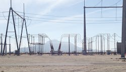
SDG&E has several 500-kV and 230-kV substations. The 500-kV Imperial Valley substation is located 10 miles (16 km) southwest of El Centro, California, within the Imperial Valley. Jointly owned by SDG&E and the Imperial Irrigation District, the Imperial Valley substation is a key facility along SDG&E’s 500-kV Southwest Powerlink, through which bulk power deliveries flow from both the desert southwest and the Imperial Valley into the SDG&E system.
Southwest Powerlink and the Imperial Valley substation are the primary paths for delivery of Imperial Irrigation District’s power purchases from Arizona. In addition, the Imperial Valley substation serves as a key point of interconnection between SDG&E and the Comisión Federal de Electricidad of Mexico, and it is a point of interconnection for several large independent power producers of both conventional and renewable generation.
The Damage Done
In 2010, the 7.2-magnitude El Mayor-Cucapah earthquake struck Southern California. The event lasted roughly 90 seconds, with about 40 seconds of strong shaking felt as far away as Los Angeles. Because of its importance to the area and significant knowledge gained through research performed by the Pacific Earthquake Engineering Research Center, the Imperial Valley substation had been seismically hardened before the 2010 event.
Although the Imperial Valley substation was forced out of service by the earthquake, the extent of physical damage to the substation was significantly reduced as a result of the seismic hardening SDG&E had completed at the facility. There was no interruption in service to SDG&E customers and minimal disruption of off-system interchanges between SDG&E and Imperial Irrigation District, Comisión Federal de Electricidad of Mexico and Arizona utilities.
The Imperial Valley substation contains both 500-kV and 230-kV switchyards with a transformer bank between the two switchyards. The damage in the 500-kV switchyard indicated in the post-earthquake survey report included the 500-kV and 230-kV transformer porcelain bushings, porcelain post insulators, porcelain surge arresters, bus support connectors, A-frame tie-down springs, freestanding surge arresters and extended corona rings on disconnect switches.
Seismic Evaluation
SDG&E set out to perform a seismic evaluation of the 500-kV bus at its Imperial Valley substation. Since the earthquake, SDG&E has repaired, strengthened and modified the 500-kV bus from the pre-earthquake configuration. The pre-earthquake and post-earthquake bus layouts are referred to as the 2010 configuration and 2014 configuration, respectively.
In this study, SDG&E was attempting to identify the seismic vulnerabilities of the 500-kV bus in the 2014 configuration and understand the likely causes of the failures observed from the El Mayor-Cucapah earthquake. More specifically, the focus of the evaluation was to help the utility identify vulnerable components (including bus supports, equipment and miscellaneous connectors) that may result in significant loss of power within the substation.
The investigation of the Imperial Valley substation’s 500-kV flexible conductor was performed for three reasons:
- To develop a structural model of bay 1 in an attempt to replicate the damage assessed during the 2010 El Mayor-Cucapah earthquake
- To determine substation vulnerabilities, if any, in bays 1 and 4 of the 2014 configuration for the 2500-year earthquake (as defined in the next section)
- To develop retrofit concepts for any vulnerabilities identified so performance can be improved to an acceptable level for SDG&E.
Study Methodology
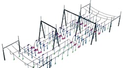
Each configuration was modeled in SAP2000 computer software. SAP2000 has the ability to model complicated geometry, nonlinear elements and material-specific damping. However, explicitly capturing progressive failure mechanisms was beyond the capability of the software. Although progressive failure analysis was not performed, the analysis sufficiently captured likely areas of vulnerability and was used to predict possible damage.
There are challenges in evaluating seismic performance and developing a strengthening process for a high-voltage substation. The engineer must have a good understanding of electrical clearances, dynamic behavior of the equipment and bus, regional seismicity, historical behavior of substation equipment and limitations of analysis methodologies.
The Imperial Valley substation was evaluated using a numerical model that accounted for the flexibility, mass and nonlinear response of each element within the substation’s 500-kV flexible conductor. The layout, equipment and conductor properties were determined using drawings, field surveys, seismic qualification reports, and materials and equipment testing data. The foundations were assumed to be rigid and soil structure interaction was not considered.
To validate the modeling assumptions and calibrate the equipment, a nonlinear analysis was performed on the 2010 configuration using scaled triaxial ground motions from the 2010 El Mayor-Cucapah event. The modeling was adjusted by modifying the conductor stiffness to match the damage observed in the post-earthquake damage surveys. Once the 2010 configuration model was validated, the substation in the 2014 configuration was evaluated using the ground motion based on a 2500-year (2% exceedance in 50 years) response spectrum.
The modeling of the equipment was calibrated by comparing accelerations, displacements and frequencies from testing data provided in the IEEE 693 Seismic Qualification reports to adjust the model to match the reported data. Insulator stiffness modifiers were applied to each type of insulator, so the displacements in the model matched the load-deflection curves provided by the insulator manufacturers. Support frames and disconnect switches were modeled as fixed bases to capture the rigidity of the support column, baseplate and anchor-bolt layout.
Conductor and Bus Support Modeling
The pre-earthquake conductor’s deflected shape was determined by taking the conductor data from a 2010 survey, photos taken prior to the earthquake and information collected from field investigations. The bus support structures included explicit modeling of the baseplates and anchor bolts. This enabled the model to capture the additional flexibility these elements introduce to the system.
Lupine wire conductor, used at the Imperial Valley substation, contains 91 individual aluminum wire strands. The IEEE Standard 1527-2006 Recommended Practice for the Design of Flexible Buswork Located in Seismically Active Areas prescribes using a moment of inertia value that falls in a range between the minimum moment of inertia calculated considering all wires separately and the moment of inertia considering the gross section, which results in a wide range of effective stiffness. A stiffness sensitivity evaluation was performed to determine the extent of which conductor stiffness affects structural performance.
The conductor was modeled using 6-inch to 12-inch (152-mm to 305-mm)-long frame elements. Based on the SDG&E’s experience, the conductor strands will have damping in the range of 10% to 12% due to the friction between the individual strands. To account for this, 8% damping was applied to the conductor material in addition to 2% systemwide damping to best capture the damping.
Analysis Results
Overall, the 2010 configuration analysis results showed a similar performance to what was observed in the 2010 El Mayor-Cucapah earthquake. Being able to replicate an existing event showed the model and analysis techniques were sound and the performance of the existing layout could be predicted with reasonable accuracy. The 2010 configuration model and analysis techniques were used to develop analysis parameters for the 2014 configuration.
The 2014 configuration analysis results show there are still seismic vulnerabilities in the 500-kV Imperial Valley substation. The analysis shows the majority of the overstressed post insulators were in the disconnect switches adjacent to drop lines or bus supports. In addition, several of the extended corona rings show stresses that may result in large permanent deflections or failures of the connections. Once a bus support connector, corona ring or post insulator fails, the system’s geometry and dynamics change, possibly leading to even higher forces in adjacent elements.
Proposed Retrofit Methods
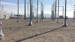
To address the vulnerabilities, several retrofit options were investigated. Because SDG&E wanted to avoid a substation outage to install the retrofits, options were limited to those that could be done in places without encroaching on electrical clearances. The first option (option A) included changing the stiffness of the bus supports to reduce the bus support response. Changing the stiffness of the bus support did help to reduce forces, but it did not substantially reduce the vulnerabilities observed.
Because stiffening did not provide the desired results, the utility considered the opposite course of action. The next proposed option (option B) included replacing the existing steel bus supports with new flexible columns. Although it reduced fundamental frequencies and accelerations, option B did not reduce vulnerabilities to the desired level, either.
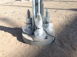
A third option (option C) was to introduce damping to the system, so as to reduce the response of the bus supports. To avoid the need for a planned outage, this concept required the bus supports to remain in the as-built position while the dampers were installed. One way SDG&E did this was to add mechanical friction spring dampers to the anchor bolts, to introduce damping through a compression couple at the base of the column.
After reviewing the first three options, the utility created option F, a configuration that combined increased stiffness of the bus support with damping to the system. This option provided a much improved performance of the system compared to option C. The post insulator demands were reduced by an average of 40%, while the disconnect switch insulators were reduced by a modest 5% to 10%. The bus support connectors also experienced an average reduction in demands of 43.2%.
A Combination of Options
Both options C and F were selected by SDG&E because of the substantial reductions in demands on both the insulators and bus support connectors. Option F was used at the end of each bay, and option C was used at all other bus support locations.
However, options C and F did not completely eliminate all potential damage for the design-level event. In all, 22 insulators and 17 bus support connectors remained overstressed. In the locations where damage was still seen, the typical demand to capacity ratios (DCRs) were 1.00 to 1.50. This was an improvement, as the DCRs of these elements in the 2014 configuration were often in excess of 3.0.
In addition, because the spring dampers are not a fully self-centering system, there will likely be some residual displacements of the support posts after significant wind and seismic events. The support posts can be replumbed by recalibrating the pre-tensions in the springs after the event. The residual displacements are not expected to affect the operational performance of the substation.
To achieve operational performance in the design-level earthquake, some additional modifications were recommended to the system in addition to implementing the option F retrofit scheme. It was recommended a three-phased approach be taken over the next several years to strengthen the 500-kV switchyard, moving it to an operational performance level under a design-level (2500-year) event.
In the first phase, the mechanical spring dampers and stiffener plates will be implemented as described in retrofit option F. The second phase will focus on replacing insulators on the six 2002 vintage disconnect switches in bay 2. The third and final phase will be to develop a new design for bus support connectors and spacers, and replace them throughout 500-kV switchyard.
In addition, SDG&E performed full-scale testing to validate its modeling assumptions and conclusions. The testing was completed in 2015, and the results showed the utility’s assumptions were reasonable. However, SDG&E did learn the conductor stiffness is not consistent over its entire length. As a result, the utility recommended the conductor stiffness be reduced to 30% of the gross moment of inertia when moving farther from the supports. With this information in hand, SDG&E continues to implement these recommendations to improve overall seismic performance of the substations within their system.
Craig Riker is the team lead for the civil-structural engineering-substations group at San Diego Gas & Electric Co. He is a registered professional engineer in the state of California. Riker is the vice chairman of the IEEE 693 Standard Committee and participates as a member of the EPRI’s Substation Seismic Study consortium.
Scott Howard provides innovative and cost-effective engineering solutions for WRK Engineers Inc.’s clients. With 16 years of structural engineering and seismic strengthening experience, Howard brings a high level of expertise in IEEE 693, ASCE 31 and ASCE 41 to his work. His experience includes seismic strengthening, design and qualification for mission-critical facilities. His hands-on involvement in projects ensures their success through quality control and superior communication with the owner and others on the project team.
