On June 16, 1964, a magnitude 7.5 earthquake rocked Niigata, Japan. Though Japan had seen its share of earthquakes, this one was different. Buildings and structures were toppled intact and large sand boils appeared throughout the affected region. An investigation found most of the structures failed because of bearing capacity failure. The sand boils were the result of groundwater being pushed up from below due to increased pore pressure caused by the settling sands.
Never before had an earthquake of such magnitude hit an area so susceptible to vibration. Being a coastal city, most of the structures were built on saturated loose sands. The combination of vibration and saturated loose sands was a recipe for widespread destruction because of foundation failures. This event sent a wake-up call to structural engineers and geologists around the world about the devastating effects of liquefiable soils.
Soil Liquefaction
Technically, soil liquefaction is the phenomenon in which loose soils are subjected to sudden lateral loads, such as during an earthquake. The soils collapse to a denser state and may cause a loss of bearing capacity, extensive permanent lateral displacement and surface settlement.
The highest risk for soil liquefaction is when there is fine or loose sand, high groundwater, seismic activity, or any combination of these. During an earthquake, vibrations cause soil grains to reorient, consolidating some soils and increasing pressure on the water trapped in the soil pores. The increased pressure causes the water to flow through the sand, creating a momentary quicksand condition. Even the briefest change in soil condition can spell disaster for structure foundations.
The Utility Impact
While states on the West Coast, such as Alaska and California, are well-known for earthquakes, the U.S. Geological Survey indicates most of the United States is subject to seismic activity. Not all seismic events create liquefiable conditions; however, electric utilities, including Public Service of New Hampshire (PSNH), have determined the risk is significant enough to warrant safeguards against these dangers, particularly in plants and substations.
In the wake of the Fukushima, Japan, earthquake in 2012 and the resultant nuclear plant damage, utilities in New England are requiring facilities to be evaluated using a design earthquake with a return period of up to 2,500 years. In New England, this equates to a magnitude 7.0 seismic event.
PSNH has taken steps to address conditions under which soil liquefaction in such an earthquake could occur and how it could potentially undermine its substation equipment foundations. A PSNH design review team and its consultant TRC Companies Inc. reviewed the geotechnical conditions at a PSNH site and developed a design approach to address this geotechnical challenge.
The Site
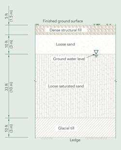
The proposed site is underlain by stratified silt and sand deposits with the groundwater approximately 10 ft (3 m) below grade. It was estimated a magnitude 7.0 seismic event would result in settlement of up to 14 inches (356 mm) for the substation structures. After weighing the differential cost and risk, PSNH decided designing for the magnitude 7.0 seismic event was justified.
Design Approach
The design team considered two approaches: in-situ densification and deep foundations.
The in-situ densification approach included consideration of vibroflotation and dynamic compaction. The first option, vibroflotation, is a technique that approximates, in a localized area, the soil vibration that would occur during an earthquake. A large vibrating probe is pushed into granular soil, along with a means for extracting water from the soil. As the probe vibrates, the sand particles are displaced and densify while the water flows out of the sand. The probe is then moved to an adjacent area and the process repeated. The second option, dynamic compaction, involves repeatedly dropping a large weight onto the ground surface, physically forcing the soil to consolidate.
Both of the in-situ densification options were dismissed because of project time constraints and the likelihood that several rounds of consolidation and extensive subsurface testing would be needed before an acceptable level of densification was achieved.
Given the time constraints and the potential cost of the in-situ densification approach, the team selected the deep foundation approach. Deep foundations would provide reliable stability during seismic events with predictable cost and time certainty.
Deep Foundation Design
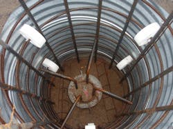
After this decision was made, the design team had to address basic design questions such as what type of deep foundation to use. Each deep foundation option — steel H-piles or round piles, wood piles and drilled caissons — presented its own distinct advantages and disadvantages. Despite a plethora of information demonstrating the longevity of wood piles in various environments, wood piles continued to be viewed with suspicion and were eventually dismissed as an option. The drilled caisson option was dismissed because of cost factors. This left steel piles as the only viable option.
Critical pile selection criteria required evaluation of the soil conditions and earthquake loads. The site soil was stratified, with the thick layer of liquefiable soil below approximately 15 ft (4.5 m) of loose sand and dense structural fill. The stratification required the pile bearing layer to be the dense till or ledge underlying the site. But, how would the structure loads and the soil layers above the bearing layer react during an earthquake? What guidance was available from applicable codes, standards and industry research?
Intuitively, during an earthquake, the liquefiable soil would act as a boundary layer, somewhat limiting transmission of lateral movement from the bearing strata to the overlying sand and structural fill. One could assume the relatively stable upper sand and structural fill layers would tend to provide lateral support against pile buckling within those soil strata.
Review of the International Building Code and American Society of Civil Engineers 7-05 confirmed this intuition. ASCE 7-05 considers the pile cap to be braced laterally if restrained by competent rock or dense granular soil having certain seismic-response characteristics. The upper-soil strata possessed the required characteristics, so lateral stability of the upper portion of the pile foundations was determined to be adequate.
However, lateral support of that portion of the piles in the liquefiable soil still had to be addressed. Liquefiable soil is considered a fluid soil. The 2009 International Building Code states that any soil other than fluid soil “shall be deemed to afford sufficient lateral support to prevent buckling” of piles. Further research found several documents that addressed pile buckling in liquefiable soil. The research papers indicated buckling of pipe piles during a seismic event has never occurred on hollow pipe piles loaded to half of the allowable buckling load. Other industry documents provided guidance for the design of similar piles filled with concrete.
These guidance documents were used to establish the primary design criteria applicable to the pile sections in the liquefiable soil and led the design team to select pipe piles for installation.
Loading Regime
Having identified the likely soil movement, established critical stability parameters and selected a pile type, the design team estimated the various loads that would be applied to the piles during the design earthquake. Unlike most substation structure foundations, in addition to the loads from the equipment and fault currents, the pile system had to be designed to withstand the loads applied by the overlying sand and structural fill.
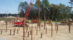
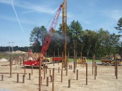
The pipe piles were driven through the sand layers and embedded at least 5 ft (1.5 m) into the underlying stiff glacial till. The embedment anchored the base of the pile from shifting and provided stiffness against lateral deflection. The loads transferred through the pile and into the bearing strata include the weight of the equipment, lateral loads from wind, fault force loads and overturning moments.
In addition, the liquefiable soil would not bear the weight of the soil above it during a seismic event, so skin friction between the overlying soil and the pile would cause the weight of that soil to be transferred through the pile into the bedrock. This is a phenomenon called “dragdown.”
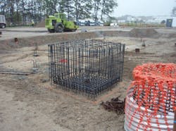
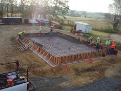
Although it was determined that the soil around the pile cap and pile would provide lateral stability against buckling, lateral movement would still occur during a seismic event. Structures having more than one pile were designed to provide rigidity by transferring the loads through the pile cap, causing the piles and pile cap to act as a single rigid body.
Small Equipment
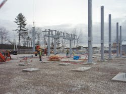
One familiar with substation design might ask, “Was more than one pile provided under each small structure such as the lightning arresters, voltage transformers or circuit breakers?” The answer is no. Deep foundations would only be justifiable if a cost-effective approach could be engineered. Single-pile foundations with appropriate section properties proved both cost-effective and structurally effective.
The PSNH design team determined that a lateral foundation deflection of 1 inch (25 mm) in any direction at the ground surface could be tolerated without long-term impact on the substation operation or safety. Knowledge of the soil movement and load transfer during seismic events allowed for the design of single-pile foundations for the smaller substation equipment. As with the other deep foundations, these piles rely on toe-in depth to anchor the pile and section properties to resist the applied loads and lateral displacement.
Corrosion Considerations
Finally, reliance on so much steel exposed to the soil, water and stray electrical currents caused concern for the longevity of the structural systems. Review of basic cathodic engineering principals and consultation with knowledgeable cathodic engineers indicated this potential problem could be addressed through application of careful isolation and corrosion allowances. A corrosion allowance
is a thickness of steel, typically 1/16 inch (1.6 mm), which is included in the thickness of the pile wall but is not considered for structural strength.
It is standard practice in substation design to ground all of the steel in a common, interconnected ground grid so everything in the yard is at an equal potential. In this case, tying the steel piles, pile cap reinforcement and structure anchor bolts into the ground system would provide an excellent grounding system but could also destroy the foundations, piles and copper ground grid through galvanic corrosion. Not only would this system promote current flow into the foundation system and increase the potential for accelerated corrosion of the piles, but the electrical stress during a fault could cause concrete spalls and other foundation damage.
The design team considered two different approaches for addressing potential corrosion and grounding:
- Bond all of the steel together after adding an excessive corrosion allowance to the pile wall thickness
- Electric isolation of the metallic foundation components.
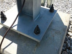
The corrosion potential was addressed by applying a reasonable corrosion allowance and isolating all aboveground structures from the underground steel foundation system (piles, pile cap and anchor rods). The structures were anchored to the foundations using isolation gasket kits typical of what is used in pipeline cathodic protection isolation.
The isolation gasket kits were selected to provide dielectric properties sufficient for the fault currents anticipated at the station.
In addition, touch-step potentials between the exposed end of the anchor bolt and aboveground structures were eliminated through application of heavy-duty shrink-wrap tubing applied over the top of the anchor bolts. Again, this material was selected to provide appropriate dielectric insulating properties. Other precautions included careful placement of the ground grid conductors away from the structural steel piles and pile cap reinforcement. Additional shrink-wrap and other methods were employed, where necessary, to ensure isolation of the grounding and structural systems.
Mission Accomplished
PSNH and TRC were able to design a cost-effective foundation system that will ensure reliable service for the full duration of the facility’s 50-year design life, even if a 7.0 magnitude seismic event occurs.
Alan Wironen ([email protected]) is a principal civil engineer with TRC Engineers, Augusta, Maine, responsible for technical oversight and coordination of power transmission and substation projects. He is a retired Navy Civil Engineer Corps officer with more than 30 years of engineering experience and several engineering degrees. He is a professional engineer.
Daniel Butler ([email protected]) is the manager of civil and transmission engineering for TRC Engineers in Augusta, Maine. He was the lead civil engineer and engineer of record for the Thornton project. He has 25 years of broad-based civil/structural design experience, including extensive experience in EPC projects. He holds a BSCE degree from the University of Maine and is a registered professional engineer in almost
30 states.
Philip Massicotte ([email protected]) is a senior engineer with 30 years of experience with Public Service of New Hampshire. He was the lead PSNH civil engineer on the Thornton project. He holds a BSCE degree from the University of New Hampshire.
Companies mentioned:
Public Service of New Hampshire| www.psnh.com
TRC Composites Inc.| www.trcsolutions.com
