Editor's Note: Speakers at T&D World Conference Exhibition 2023 will cover the topic of remote line inspections and drones. For more information, please see our conference program. You can register for our event here.
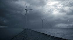
In January 2014, a fatal accident involving a helicopter ambulance occurred in Sollihøgda, Norway. An investigation into the accident concluded the helicopter hit an overhead line that was difficult to see from the air because it had no aircraft warning markers (AWMs) installed. As a result of this finding, that same year the Norwegian Civil Aviation Authority updated its regulations on marking flight hazards. This update directly affected Statnett SF, the transmission system operator (TSO) responsible for the design, construction and operation of the Norwegian transmission system. With operating voltages of 420 kV, 300 kV and 132 kV, Statnett’s overhead lines span more than 11,000 km (6,835 miles).
According to the updated regulations, all existing overhead line spans with a height aboveground of 60 m (197 ft) or more for over 100 m (328 ft) in length must be marked with AWMs. To fully comply with these regulations, Statnett would have to install more than 3000 AWMs on existing unmarked transmission line spans. Additionally, the specification for the AWMs was updated to require all markers be covered with reflective sheeting on at least 50% of their outer surface. As a result of this new requirement, all existing markers on Norwegian transmission lines would have to be replaced.
The TSO would have a limited number of summer seasons in which to complete the necessary work before the regulations went into effect. Therefore, it needed to find a more efficient way to install AWMs.
Existing Installation Method
The primary method used to install AWMs in Norway at the time was from a line cart or during the restringing of shield conductors. It was not considered feasible to meet the necessary deadlines using these methods, so alternative methods were sought. A workshop was held with subject matter experts to review different AWM installation methods being used around the world:
- Working from a platform attached to a helicopter skid
- Working from a platform suspended beneath the helicopter
- Robot-based solutions and more.
These techniques were assessed based on three criteria:
- Health and safety, with ideally no work at height
- Speed of installation (10-plus markers per day or at least one span a day)
- Cost effectiveness, with the goal of reducing the cost per marker installed by more than 20% compared to the current cost. Eliminating the need for outages was considered the most cost effective.

Installation Robots
The goal of the installation robots project was to investigate the possibility of using robots to install markers on existing unmarked spans that met the requirement for marking. The solution would need to be safe, fast and cost competitive compared to commercially available alternatives. It had to be tested and ready for use within 12 months, so time restraints were a significant factor in many design decisions. This work was undertaken with support from Best Paths, a European Union (EU) funded project consortium. One of the goals of Best Paths was to develop innovative live-line working techniques for use on existing alternating-current overhead transmission lines.
In the years prior to the updated regulations in 2014, an extensive type-test program had been carried out for markers. In some areas, Norwegian transmission lines are exposed to heavy icing, up to 100 kg-m (67.2 lb-ft). This resulted in a high requirement for marker slip-loads. In addition, because of terrain topography, some overhead line spans are exposed to very high levels of Aeolian vibrations. This high level of exposure to vibrations in addition to fatigue type tests resulted in all approved markers being installed on armor rods or using elastomer lined clamps. The type-test program for markers is time consuming because it includes a 25-week artificial ageing test and an Aeolian vibration fatigue test. Therefore, because of time restraints, the robot would need to work with one or more of these already type-tested and approved markers.


Statnett’s Robot
The first step was to define the three key requirements for the AWM installation robot:
- The robot had to work with the AWM markers that had already been approved and type-tested with only small modifications. Markers with elastomer-lined clamps were chosen to avoid the need for robotic installation of armor rods.
- The robot had to be hung beneath a helicopter. Many tower locations in Norway have limited or no access by vehicle. Tower locations that require AWMs are typically in more mountainous regions.
- The AWMs had to be installed one at a time to minimize complexity.
Design work started with a proposal for the operating principal for AWM installation:
- The AWM would be designed in two halves that could be lowered onto either side of the overhead line shield conductor.
- The AWM could be installed using four T-bolts. The T-bolts would be inserted into a slot on one-half of the AWM, and when the two halves are pressed together, they would pass through slots on the opposite half.
- The T-bolts would be rotated 90 degrees, where they meet an edge that prevents further rotation.
- The torque being supplied would continue tightening the nuts until reaching the required value.
A partner company, experienced with designing and manufacturing industrial robots, was invited to join the project team. The following solution was proposed:
- A robot would be lowered onto the shield conductor and two sensors, one on either side of the robot, would register when the weight of the robot was resting on the shield conductor.
- When the robot’s wings sink, the weight on the wings would push the two halves of the AWM together and a third sensor would register when the two halves were pressed together.
- An adjustable time delay would be used. If the robot were lifted before the time delay finished, the installation process would start again without error. This delay would give the pilot time to ensure the robot and helicopter are positioned correctly before the installation starts.
- Finally, motors would rotate and tighten the four bolts to the required torque and signal lights would indicate when installation was complete.

Prototype Testing
A full-scale prototype and AWMs from two different manufacturers were produced for testing. Then 3-D computer models were used to verify compatibility and confirm dimensions before the prototype robot and AWMs were manufactured. The design proposed for the robot placed requirements on the AWM clamp dimensions. While clamp manufacturing techniques placed limits on the thicknesses and orientations of some surfaces, in some cases, solutions were technically possible but changes were made to reduce the long-term manufacturing costs of the AWMs. For example, the number and size of surfaces that required machining was kept to a minimum. In some cases, 3-D printed models of clamps were used to confirm compatible AWMs were manufactured.
Prototype testing initially took place indoors using a crane. AWMs were installed on conductors with three different diameters on both a horizontal span and a span with a 30-degree inclination. After indoor testing, the prototype was tested outdoors using a helicopter on a full-scale 300-kV test transmission line. The operation was classified as “precision delivery above-ground level,” which requires certain pilot qualifications and experience.
Use of the robot was described by the pilot as a demanding but repeatable operation.
Installation Projects
Following prototype testing, the robot and AWM designs were updated, and three robots were built for use in AWM installation projects. A test stand was built to enable testing of the robot directly prior to the installation on the shield conductors commencing. The maximum distance allowed between markers is 70 m (230 ft). Several different solutions for measuring the distance between each AWM were used. The first was GPS based and another solution was to have personnel climb to the top of a tower and measure distances using a range finder.
A dedicated position AWM robot also was built that could be delivered to and collected from the shield conductor using a helicopter. It was remote controlled, could measure the distance it had traveled along the wire and could move between the AWM locations in less than a minute. This was judged to be the most effective solution.

The majority of AWMs installed using robots were done so by contractors who provide price offers based on two different methods, their own preferred method and the use of the robot. The robot is only chosen if it is the most cost-effective method. Several factors influence the cost effectiveness of the different installation methods, including the location of the transmission line in Norway, the distance to the nearest airport and accessibility by road to tower locations, to name a few. The largest savings from this project have not been those associated with the AWM installation robots but rather the pressure in the market caused by the introduction of a new and cost-competitive alternative.
The robots are now included in the list of products available for hire by Innova, the company that assisted with both the robot design and production. The AWMs were manufactured by Mosdorfer GbmH, a member of the Knill Energy Holding, and Proizvodna OSO d.o.o., a member of the Dalekovod Group. The drawings that define the interface between the robot and AWMs are publicly available, making it possible for alternative suppliers to produce robot-compatible AWMs.
Project Progress
To date, over 400 AWMs have been installed using the installation robots, 15 on a custom-built test stand, 40 on test spans and 359 permanently installed on overhead transmission lines — nine of which were installed with the line in service as a live-line work. Installation takes approximately one minute, with 30 AWMs a day found to be realistic using two robots and one helicopter. If more than 30 AWMs a day will be installed, then an additional pilot is recommended. The failure rate of the final solution was less than 1% and — after the adjustable time delay was increased, giving the shield conductor more time to come to rest before the installation process started — no more installation failures occurred.
The robots designed and produced for this project have now been used to install hundreds of AWMs on existing unmarked Norwegian overhead transmission lines. Developed under very tight time restraints, the solution is reliable and cost effective as well as reducing the need for personnel to work at height.
Boris Adum ([email protected]) holds a MSME degree from the University of Zagreb in Croatia. He worked for 10 years at Dalekovod d.d.o. on testing and in the research and development in the mechanical laboratory before joining Statnett SF in 2012. Currently, Adum works in the transmission line department at Statnett SF on overhead line and accessories specifications. He has participated in several research and development projects and is an active member of CIGRE.
Livia Dickie ([email protected]) was awarded bachelor’s degrees in electrical and electronic engineering and computer science by the University of Western Australia. She conducted a university honor’s project investigating the use of robotic solutions in unmanned power transmission substations. Dickie has research and development experience from working for the Defense and Science Technology Organization (DSTO) in Australia and also worked for four years at the Australian transmission system operator, Powerlink. She joined Statnett SF in 2010, where her current responsibilities include substation control systems.