Integration of DER Smart Inverters for Distribution System Operations
Updated interconnection standards for Inverters
To ensure continued reliable operation of the distribution grid with rapid growth of inverter-based DER, and to utilize smart inverter functions in grid operations, the DER interconnection standard (IEEE 1547) needed to be updated. Consequently, the revised standards - IEEE 1547-2018 and its corresponding test standard IEEE 1547.1-2020 were published. A variety of stakeholders including electric cooperatives, municipal utilities, investor-owned utilities, and regulatory authorities such as Public Utility Commissions (PUCs) have started to adopt the updated standards. As adoption of this standard started, and exploring the use of smart inverters as grid assets in addition to their primary function of converting DC to AC power increases, the settings for these inverters might need to be changed to comply with the new standard and to provide the grid services, such as voltage regulation, and voltage and frequency ride-through.
The impact of rapid DER growth
Cooperatives have been experiencing growth of DER in their service territories. As these standards become more widely adopted, this will impact how these resources are managed and how DER can provide grid services. At higher DER penetration levels, smart inverters connected to these DERs can assist cooperatives in ensuring optimal performance of the grid, and high quality and reliability of electric service to their members. For example, cooperatives can implement alternative settings on smart inverters for improved voltage regulation on distribution feeders. Manufacturers will soon have to incorporate these standards into their inverters and certify them for compliance.
What grid operators need to know or do
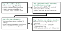
NRECA has developed a framework that can help cooperatives determine the changes in settings needed to comply with the updated IEEE standard, and assess the impact of changing the operational settings of smart inverters on rural distribution systems. NRECA partnered with the National Electric Energy Testing, Research & Applications Center (NEETRAC) and two cooperatives to conduct field-tests. We then shared the findings regarding how to determine the smart inverter settings to comply with the standard and achieve the benefits of using smart inverters for grid services. The project steps include developing the framework, conducting simulations with historical grid data, simulating inverter performance using distribution powerflow tools, designing test plans, implementing these test plans in the field, collecting grid data, analyzing the data to understand the impact of the alternate settings, summarizing results and lessons learned, and sharing them with the cooperatives and other stakeholders.
Framework/Steps
This is the first part of a two-part series of articles. Part 1 focuses on the framework development and lessons learned from the simulations to develop the test plan. Part 2 of the series will focus on the two cooperative’s field-testing methods, procedures and data analysis.
Steps 1&2: Pre-test Data Collection & Simulation studies
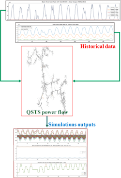
The purpose of conducting the simulation studies is to help determine the impact of potential alternative settings on the distribution grid, so that the test plans that are developed will be credible and realistic. Actual time series historical data (solar generation and load) was obtained and used from both test sites. The inverter’s different settings were modeled in the powerflow simulation to mimic the operation of the inverters and to understand the impact under multiple loading and generation scenarios.
Simulation Cases
- Base Case (Default Settings)
- Unity PF/Default general setting
- No Voltage Regulation
- Case-I
- Fixed PF Inductive
- Fixed PF Capacitive
- Case-II
- Volt-Var Curve (with & without dead-band)
- Considering suggested curves from the inverter manuals
- Case-III
- Volt-Watt Curve (if available)
Data gathered from the simulation results:
- Voltage profile along the feeder and its distance from PV system and the substation
- Impact on losses
- Power Factor at the substation
- Impact on voltage regulating devices operations
Lessons Learned From the Simulations
The simulation results and outputs gave the project team confidence and developed a sense of expectation about the response of changing the PV inverter settings. The simulation results also helped identify a set of alternative settings to be employed by the co-ops. However, simulations have limitations in showing the actual response of the system in the field. To be able to assess and analyze the actual impact of voltage regulation settings on the distribution system, the project team developed a testing protocol to be implemented in the field, collected the data, and performed the analysis.
The deployment of inverter-based (i.e. smart inverters) DER has increased considerably in recent years. Utility experience has demonstrated that smart inverters have the potential to enable DER to support grid needs when combined with new capabilities that allow full utilization of the functionalities of smart inverters in operating the distribution grid. Therefore, DER have the potential to enable more flexible operation of distribution systems with higher DER penetration, as well as provide grid services at the local level that were not available before. The updated IEEE-1547 interconnection standard enables leveraging the functionality of inverters in a standardized and predictable manner, providing greater benefit to the utility, in addition to their primary function.
The developed framework incorporates simulation tools based on historical data, test plans, and analysis of the data collected in the field to accurately determine the impact of the alternative inverter capabilities and settings added to the 1547-2018 standard. Outputs of the analysis have been used in assisting co-ops with adjusting constant PF, volt-VAR, and volt-Watt setpoints for utility scale assets. NRECA also conducted field tests to assess the impact of these settings on rural distribution circuits.
Steps 3 & 4: Test plan, Field Tests and Post-test Data Collection & Analyses
NRECA and NEETRAC developed the test protocols for the testing sites after collecting the preliminary data on specifications of the inverters. If there is a need to physically change the settings and collect the measurements in the field, that can be performed remotely. After the testing protocol was developed, NRECA and the co-ops reviewed and revised the test plan. NRECA and NEETRAC worked with the co-ops to arrange a site visit, followed by an actual test protocol/program. The details of the field tests, the testing program, the data collected in the field and the data analysis will be included in the second part of this series.
Part 2 of the series will focus on the two cooperative’s field-testing methods, procedures and data analysis


