Hydro-Québec is developing advanced technologies for electric vehicle engines and batteries. At the same time, it has been rapidly building out a charging stations network, called the Electric Circuit, specifically for electric vehicles (EVs).
The utility’s contribution to transportation electrification is part of its commitment to provide guidance on initiatives that support sustainable development goals, including the reduction of greenhouse gas (GHG) emissions in Québec, Canada, through sourcing 98.8% of electricity from clean, renewable sources. To support these initiatives, the utility has been participating in feasibility studies and pilot projects that focus on the impact of EV charging stations on its distribution network.
The Electric Circuit
The Electric Circuit is Canada’s first public charging network for EVs. It offers both 240-V and 400-V charging stations, which are installed in the parking lots of numerous partners across Québec and northeast Ontario. Hydro-Québec’s deployment of charging infrastructure to support the arrival of EVs has been a major undertaking. Since the Electric Circuit project launched in March 2012, more than 340 private and institutional partners have joined the network, which now has more than 55,000 members.
The number of Electric Circuit charging stations and areas served continually are increasing. Today, the network comprises more than 2000 charging stations. Approximately 90% of them are level 2 EV chargers (7.2 kW at 240 V) and 10% are direct-current fast-charger (DCFC) EV charging stations (50 kW at 400 V), the majority of which are located in the province of Québec. Soon, dc ultrafast-charging stations (DCUFC) — with capacities ranging from 150 kW to 350 kW — will be added.
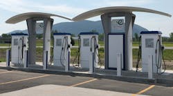
Recently, some double stations — or superstations — were deployed. These state-of-the-art superstations offer four 50-kW fast-charging stations that can charge vehicles simultaneously. Designed by a Québec firm, the superstation has an adaptable configuration that renders its installation optimizable, making possible both the addition of charging stations and the integration of new, more powerful technologies. The concept also offers an attractive, easily recognizable visual signature with a well-lit background.
Evaluating Stations
The charging stations and devices under test (DUT) are from two vendors. They each require a three-phase 480-V ac power supply. The main component of the DUTs is a power convertor (or several of them), providing power to the EVs at a voltage between 200 V dc to 500 V dc. The DUTs were equipped with CHAdeMO, a trade name that stands for move using charge, and combined charging system (CCS) handles. The EV models tested were the Chevrolet Spark from General Motors and Leaf from Nissan.
All models of DCFC EV charging stations (50 kW at 400 V) underwent rigorous climate testing at Institut de recherche d’Hydro-Québec (IREQ), the utility’s research institute. These units were tested mostly for winter climate to see how they withstand very cold weather and icy conditions.
They also were submitted to a power quality impact evaluation. Equipped with power electronic interfaces, these charging stations can cause voltage waveform distortions. The distortion levels were measured during the power quality (PQ) tests to assess and determine whether they exceeded the thresholds suggested by the international standards of the International Electrotechnical Commission (IEC) and IEEE.
The evaluation of the charging stations impact on power quality is a three-phase process scheduled over several years:
- Phase 1 (2018) — Laboratory testing on DCFC (50 kW at 400V) to assess environmental and PQ impact
- Phase 2 (2019) — Field testing on DCFC (50 kW at 400 V) to assess PQ impact
- Phase 3 (2020 and beyond) — Field tests on DCUFC (100 kW, 150 kW and 350 kW at 400 V or 800 V) to assess PQ impact.
These tests were a requirement for the Electric Circuit and will enable Hydro-Québec to understand the impact of EV charging stations on its distribution network.
Laboratory Testing
The laboratory tests were conducted in 2018 and included both environmental and PQ assessments. To perform the tests, two setups were built, one for the environmental tests and the other for the PQ impact tests. Both setups used the same electrical circuit comprising a fused switch (600 V, 400 A), three-phase autotransformer (600/480 V and 225 kVA) and fused switches (480V, 125 A and 480 V, 100 A).
The setup for the environmental tests included a climate chamber, and the PQ monitoring and disturbance recording were performed with two PQ analyzers. The Hioki 3196 and Hioki 3198 were equipped with the Hioki 9661 (500 A) and Hioki 9694 (5 A) current clamps.
The environmental tests were conducted in April 2018 and May 2018 in IREQ’s mechanical and environmental tests laboratory. Then following tests were completed:
- Rain test, per National Electrical Manufacturers Association (NEMA) 250-2003
- Ice test, per IEC 62271-102
- Dry and cold heat test, per IEC 68-2-1/2-2007
- Wet heat and frost test, per IEC 68-2-38-1974.
The environmental test program was customized and optimized according to a request from the Electric Circuit project analysis committee. Charging stations from different vendors were submitted for environmental tests and two also underwent the PQ tests.
The PQ impact evaluation tests included monitoring the power supply of each charging station during idle periods (no EV charge) and during EV charging periods based on a three-stage process: the start-up, full charge and end of the charging process. For reasons of coherence, homogeneity, uniformity and regularity, several EV charging sequences have been carried out and monitored on the Spark and Leaf EVs.
All the voltage and current measurements were taken from the primary side of the autotransformer to evaluate the impact on the quality of the voltage waveform on Hydro-Québec’s distribution network. The minimum (Min) and maximum (Max) voltage and current root-mean-square (rms) values were recorded during idle and on-charge periods. The phase-to-neutral voltage levels, recorded during the inactive and active periods of the charging stations, were stable with fluctuations up to 4 V between the Min and Max values.
The Max currents measured during the on-charge periods did not exceed 51.2 A rms, which represents around 25% of the capacity of the autotransformer in normal operation. The Min values of currents corresponding to idle periods were lower than 2 A rms, but their harmonic content was significant. The voltage and current waveforms recorded in the idle periods of the charging stations were similar for both DCFC stations.
The start-up involves specific operations with the power electronics interface of the charging station, which likely includes a capacitor bank engagement. The peak of the current transient reaches 250 A (crest value). The elevation of the charging current is controlled and done sequentially. The full charge current is reached after about 25 sec and varies slightly around 50 A rms during the full charge period.
Ending the charging process can be done by the operator at any moment, and the magnitude of the current drawn by the DCFC station decreases sharply within a cycle or by DCFC station microprocessor when the EV battery is fully loaded. The decrease rate is slower and the third stage takes 0.5 sec to 1 sec. The voltage and current waveforms recorded during the full charge period show very small harmonic distortions on the voltage side and higher harmonic distortions on the current side. However, neither one exceeds the recommended harmonic limits.
The total harmonic distortion (THD)—the minimum, average and maximum values taken at the primary side of the autotransformer—were quite linear over the charging process. Slightly lower values were measured during the idle periods before and after the charging process. The THD is less than 1.12% when the charging station is inactive and lower than 1.27% when it charges the EV.
The total demand distortion (TDD)—the minimum, average and maximum values—are very linear over the full charge stage. Conversely, significantly higher values, up to 94%, were recorded during idle periods before and after the charging process. The higher values were a result of the extremely low magnitude of the current fundamental when the charging station was inactive and the much higher magnitude when it was active. The inrush current calls on the charging stations had no noticeable impact on measured rms voltages, but the dominant harmonic orders are the 5th, 7th and 11th.
When the stations are on-charge, the voltage unbalance (Uunb) is lower than 0.9% and the flicker Pst does not exceed 0.34%.
Communication Errors
Charging is a controlled process involving communication between the microprocessors of a charging station and EV, which exchange information. Several times at the beginning of the charging process, there were communication errors forcing the charging station microprocessor to stop the process. Five such events occurred involving both charging stations.
The following solution fixed the problem:
- Disconnect the connector from the charging station
- Start the electric vehicle
- Stop the electric vehicle
- Reconnect the connector of the charging station
- Restart the recharge.
It is possible rapid successions of charging stops and starts may have contributed to the communication errors.
Field Testing
Field tests are being performed in phases 2 and 3. The stations are supplied by a dedicated three-phase autotransformer (600/480 V). A PQ monitoring system, PQube from Power Standards Lab, was connected between the primary side of the autotransformer and the secondary of a three-phase delta-connected (25-kV, 600-V) medium-voltage power transformer.
The PQube monitors measure and record PQ disturbances related to the charging stations, including the harmonic emissions (< 2kHz) as well as the high frequency or supraharmonic emissions (2 kHz to 150 kHz). Permanently installed, the PQube monitors communicate wirelessly (over the cellular network) with the PQ server located at IREQ’s facility.
Phase 2 tests started in July 2019, with one of the DCFC charging stations being monitored since June 2019. The monitoring of the second station will start in December 2019.
Phase 3 tests will be performed in 2020. The DUTs will be the ultrafast-charging stations of 100 kW, 150 kW and 350 kW as well as the ultrafast charging infrastructures of 150 kW and 350 kW, each including two charging stations sharing the power. The PQ monitoring systems for phase 3 will be selected in early 2020. Three demonstration sites will help Hydro-Québec to understand the need for public charging infrastructure for future generations of EVs—not only for individual transportation but also public transit (bus) and freight (light trucks, trucks)—for more effective deployment in the future.
The tests conducted as part of the Electric Circuit project have focused on the impact of two DCFC stations on the quality of electrical supply provided by Hydro-Québec’s distribution network. The tests were carried out in IREQ’s laboratories, and the analysis of the results from the PQ tests indicated the following:
- Levels of PQ current indices related to harmonic distortion, TDD and individual harmonics magnitudes exceed the thresholds recommended by standards, when charging stations are idle and the fundamental current is very low (<2A).
- Those levels decrease to acceptable values during on-charge periods, when the fundamental current is much higher (>50A).
- Levels of voltage PQ indices are lower than the standards limits during both active and passive periods.
Acknowledgement
The author wishes to acknowledge the support and assistance given by Jean-Luc Dupré and Rosmery Rozas Puertas of Hydro-Québec in the preparation of this article.


