Albert Einstein said, “A man should look for what is, and not for what he thinks should be.” While the quote referenced the disposal of prejudices in the context of the scientific process, the same philosophy applies to today’s power system. Restated, “The grid should be operated to what is, and not to what the assumptions say should be.”
Oncor’s recent Smart Grid Demonstration Project (SGDP) — cofunded by the U.S. Department of Energy (DOE) — employs Einstein’s counsel by jettisoning assumptions for real-time information in a key area: thermal ratings for overhead transmission lines. Through the SGDP, Oncor quantified the economic costs of thermally constrained lines and compared traditional line rating methodology with real-time monitoring methods. There were several operations breakthroughs of the SGDP, and the results are already being extended to new areas.
Economic Costs
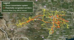
Oncor is a U.S.-regulated electric transmission and distribution service provider that serves 10 million customers across the state of Texas. The Oncor transmission system consists of approximately 1,500 circuits (Figure 1). The needs of the grid have tremendous variability across time. Texas has seen rapid load growth in pockets as a result of oil and gas developments, while wind and coal create more changes on the generation side. On top of these larger trends, pricing varies day to day, which increases the unpredictability of the load-carrying requirements on any particular line.
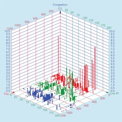
Figure 2 plots congestion over a three-year period. When congestion is displayed by date and line, the volatility of congestion in a market-driven environment is apparent. The plot shows a few lines have chronic congested behavior and the financial impacts vary from a few dollars to millions of dollars over a day’s operating period. Each bar represents a day’s financial impact for a given transmission line. Over the three-year period, approximately 200 lines would experience sporadic to chronic congestion under N-1, N-1-1 or N-2 conditions.
Since the Electric Reliability Council of Texas (ERCOT) dispatches the system to avoid contingency overloads, these constraints account for approximately US$172 million in annual congestion costs, even though the lines are seldom loaded to their limits in actual operation. If the utility could use more thermal capacity from existing lines, customer costs could be reduced not only through access to lower-cost generation but also through reduced transmission cost-recovery charges.
The data in Figure 2 points to the need for a flexible solution to meet the uncertainty of transmission grid needs. As grid topology changes — due to changes in load growth, generation (construction, mothballing, market pricing and distributed resources) and transmission grid enhancements of upgrades, rebuilds and new construction — the demand on individual transmission lines can be difficult to anticipate. Loads can appear and disappear within the planning and construction duration of a traditional upgrade or construction of a new line.
Precisely and quickly meeting the line-capacity requirements of today’s grids requires smart grid technologies. In many cases, the latent capacity within the existing transmission assets can bridge this dynamic environment.
New Monitoring Systems
A transmission conductor acts as a thermometer suspended in the air. The conductor can vary in temperature almost foot by foot because of the influence of the solar radiation, ambient temperature and wind. The dominant factor of this variability is wind. Like humans, overhead lines feel the same soothing feeling from a breeze on a hot day or the bite of a midwinter gust.
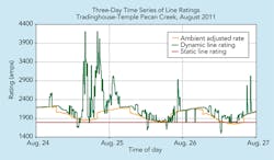
Figure 3 embodies Einstein’s admonition and shows how observation can yield insights not available to those who assume. The graph shows three different line ratings plotted for a three-day period: static, ambient adjusted and dynamic.
Traditionally, utilities have used a static line rating (SLR), which is a fixed rating based on a set of severe climatic conditions. SLRs often assume 0.6 m/sec (2 ft/s) of wind perpendicular to the line, 40°C (104°F) ambient temperature and full summer solar levels.
Since 2004, ERCOT transmission operators have had the option to submit an ambient adjusted rating (AAR), which follows the ambient temperature variation but maintains the same severe wind and solar levels as the static rating. The AAR generally follows the diurnal trend of the day and night temperatures.
Finally, the dynamic line rating (DLR) is shown in green as it adjusts for the wind, solar and ambient temperature variation throughout the day. Note there are times when the DLR dips below the AAR and SLR. These dips occur when the wind speed is less than 0.6 m/sec and temperatures are higher than the static or ambient adjusted base temperature.
The curves in Figure 3 can be determined by using tension monitoring or conductor position monitoring in real time to establish the average temperature along the length of the conductor. Then, this effective temperature is used to calculate the effective average wind speed. Combining the effective average wind speed with real-time ambient temperature, solar levels and loading on the line, the dynamic rating for the designed maximum operating temperature of the line can be calculated and applied during operations.
Conductor performance follows the physics and mathematical model of a catenary curve. The tension, sag and temperature perform according to a mathematical model. Knowing one or two of the parameters allows defining the other parameters. So, knowing the position or tension of a conductor characterizes the thermal performance and allows calculation of the dynamic rating of the line. Several technologies are currently available to determine the tension or position (sag or clearance) in real time. Through measuring these parameters and ambient conditions along the line, the full dynamic performance of the line can be modeled and DLR calculated.
Economically Significant Thermal Capacity
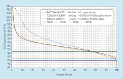
When rating data is accumulated for many months of operation, a cumulative probability curve can be determined (Figure 4). The curves differ for each of the three lines displayed because of the line’s orientation to the wind and type of terrain of the line’s corridor. Examples of corridor variation include open terrain, urban areas or tree sheltering. The graph demonstrates data for one line cannot be extrapolated to other lines. Also, a given line’s percent of static rating will vary from hour to hour. DLR requires real-time monitoring of a specific line and integration of its data into the operating environment.
Figure 4 also illustrates the percentage of time the DLR capacity is above static. Horizontal lines on the graph demark the 105%, 110% and 125% levels of capacity compared to the static rating. Static ratings are exceeded more than 98% of the time. Oncor currently applies an increment cap of 25% above SLR to account for relay settings and the next-limiting elements along the line section, such as current transformers, switches and wave traps.
Many lines experience operating limits in the range of a few percent above the SLR or AAR. State estimator models are applied for N-1 contingencies in which the post-contingency loads must be lower than the allowable line rating. Therefore, typical operation of the grid begins adjusting generation such that the N-1 contingencies remain in a reliably stable mode.
During the course of the DOE SGDP, studies found that 5% to 10% incremental capacity on selected lines would reduce a significant proportion of congestion costs. As Figure 4 shows, without DLR, 90% of the time, the additional capacity would be hidden and unused. DLR has revealed more than sufficient capacity to measurably improve grid economics.
From Sensor to Market
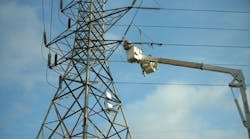
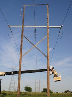
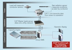
Figure 5 shows a typical field application of a tension monitoring system on a wood H-frame. This example would be one of the remote sites identified on the top line of the deployment schema shown in Figure 6. The remote monitoring systems feed into gathering locations at substations where they are introduced into the supervisory control and data acquisition (SCADA) network or as an option transmitted to a data acquisition system at the general office through a different communications path, perhaps cellular.
The data is fed through an algorithm to generate ratings for each monitor site and then for each line section, assessing the lowest rating for the element path. The energy management system has an automated data quality and availability assessment logic operation that determines if adequate rating data has been received for a line section and if the data is in an expected acceptable range.
If the quality checks pass, the data is posted to the telemetry system for operations. If the data quality assessment has any questions about the data or its validity, a flag alert is passed to an operations support desk for assessment. If necessary, because of logic validation failure, the ratings revert to the nominal rating system the utility uses.
This process integrates the real-time dynamic rating into the data stream used for state estimator analysis on a regular cycle (for example, two- to five-minute cycles). The integrated DLR (iDLR) provides the system with time-sensitive accurate line ratings for optimum operation.
Because the system is constantly monitoring and updating the rating based on real-time ambient and operating conditions, passing that data to the security-constrained economic dispatch (SCED) — or equivalent state estimator analysis — and using the actual line capacity for reliability and economic dispatch decisions, the iDLR system provides wide area situational awareness (WASA) that no other system can provide today. WASA maintains the cyclic assessment and adjusts the grid operations automatically to take advantage of the added line capacity to most efficiently and reliably maintain system integrity and economic dispatch.
The major accomplishment from the DOE SGDP was the market integration of real-time iDLR into the telemetry data stream used for system operations. From the field sensor to the market operator’s economic dispatch systems, real-time line ratings are constantly used to minimize customer costs. These market benefits are derived at minimal expense compared to capital investments, and with much shorter lead times. Furthermore, the transmission operator has the flexibility to respond to newly loaded lines while increasing line capacity, reducing transmission line constraints, decreasing operating room workload and providing WASA.
The Future Is Here and Expanding
Static assumptions were sufficient in an earlier era where load and generation were more predictable. Today, environmental, economic and infrastructure needs create volatility in all areas of the power system, which in turn drives the need for more operational flexibility. For thermally constrained lines, DLR technology can provide the incremental capacity needed to meet this volatility with short lead time to operation (in as few as six months), flexibility to remove and apply equipment at a different location of need on the system if needs change, and minimal operations training and workload on the operations staff.
Following the success of the initial SGDP deployment, Oncor installed a second system in West Texas to meet needs that have arisen since the original DOE grant. By discarding assumptions for observations, the grid is being modernized in a way that would make Einstein smile.
Acknowledgement
The information in this article is the culmination of a cosponsored project between Oncor and the DOE for the SGDP program. The work and article were the result of contributions by Ron Stelmak, Rob Mohr and Sandy Aivaliotis of Nexans; Gary Ragsdale, Sean Mitchem, Gerardo Trevino and Joe Loomis of Southwest Research Institute; Neal Hurst of EDM International; Steve Syracuse of Promethean Devices; and Justin Johnson, Cale Smith, Eddie Clark, Mike Juricek and Raul Espejo of Oncor Electric Delivery.
Tip Goodwin ([email protected]) is a consulting engineer with Oncor Electric Delivery and is presently with the transmission standards group at Oncor. He has 24 years of utility T&D experience from large utilities such as Pennsylvania Power & Light, Entergy and Oncor. His experience also includes 16 years in consulting engagements at GAI Consultants and PBS&J as well as R&D engagements at EPRI and Sverdrup Technology. Goodwin is a member of the IEEE Power & Energy Society and has chaired or served on several IEEE task groups, working groups and technical committees in the T&D towers, poles and conductors area. He is a member of CIGRÉ Study Committee B2 WG 06 Reliability and the U.S. technical advisor to IEC TC11.
Companies mentioned:
Department of Energy | http://energy.gov
Oncor Electric Delivery | www.oncor.com
Sidebar:
Tension: Surrogate for Temperature
The temperature of a line section can vary foot by foot because of the spatial variability of wind impinging on the conductor. Fortunately, the conductor’s performance follows the physics and mathematical model of a catenary curve, making the determination of the average conductor temperature a straightforward and simple task.
The horizontal tension of the conductor catenary from suspension structure to suspension structure will equalize as insulator strings swing to compensate for the tension imbalance as one span is heated or cooled more than another. Thus, monitoring the tension or the vertical position of the conductor captures the spatial variation of weather’s impact on conductor temperature and provides a means of determining the average conductor temperature.
Several technologies are currently available in the industry to determine the tension or sag (tension and sag are inversely related) in real time. Through measuring these parameters, the average temperature of the line can be determined and dynamic line ratings calculated in real time.
