Is Your Transformer OK?
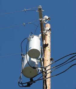
Catastrophic failure of an overhead transformer is a rare occurrence, but it does happen. Electrical systems are designed so protective devices, like fuses, operate first and protect more important devices, like transformers. A blown fuse is not uncommon and can be caused by several fault conditions: wildlife getting between energized conductors, cars hitting utility poles, lightning strikes and overloaded circuits.
Blown fuses are simply replaced and reclosed, re-energizing the line section or the transformer the blown fuse de-energized. Sometimes the fault that blew the fuse also damages the transformer. This is often apparent if there is damage to the transformer tank or the pressure relief device has blown out. But in very rare cases, the transformer fails with no outward sign. This can be a dangerous situation. So as part of Pacific Gas and Electric Co.’s (PG&E’s) continuous effort to improve safety, the utility has embraced the use of internal fault detectors on all new overhead transformers.
The Beginning
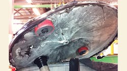
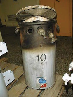
In 2000, a PG&E lineman escaped serious injury when an overhead transformer he was working on exploded. To supply energy, PG&E put up a conventional single-phase overhead transformer, which became overloaded; within a few weeks, both of its fuses blew. (For the most part, PG&E is a phase-to-phase connected system, so most transformer installations have two or three fuses.) There was no outward sign the transformer had failed, but it had. The lineman replaced both fuses, closed them into a dead short and the transformer exploded. The force of the explosion inverted the lid and then sent it flying. Fortunately, the lineman was wearing the appropriate personal protective equipment and was not hurt.
After this incident, PG&E revised its operating procedure by restricting re-energization attempts when the cause of a transformer outage cannot be determined. If there are no signs of damage to the transformer and if only one fuse is blown, then and only then do PG&E linemen replace the fuse and try to re-energize the transformer. If two or three fuses are blown, PG&E linemen assume the associated transformer has failed and replace it, regardless of its appearance.
These changes in operating procedure were a good first step, but PG&E wanted to take it further. Since the utility has more than 1 million distribution transformers, with the majority of the units being overhead units, outages happen every day. Many times the failure is obvious, corrections are easily made, and the transformer is re-fused and service restored. Sometimes it takes more investigation to uncover the cause and sometimes no cause is found, the transformer is re-fused and power is restored without incident.
Then there are those rare cases where the transformer looks fine, is refused and fails catastrophically when re-energized. Even though such catastrophic failures are atypical, PG&E looked for a way to prevent them. Then in 2001, some of PG&E’s electrical engineers went to the IEEE T&D Exposition in Atlanta, Georgia, U.S., and attended a presentation by Paul Chisholm, president and CEO of IFD Corp., about the company’s internal fault detection (IFD) device.
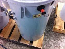
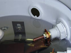
The small device mounts through the wall of the transformer case and detects any sudden rise in pressure. If that occurs, a highly visible button pops out, warning line workers the transformer has experienced an internal fault. The IFD does not activate if the internal pressure rises slowly, only if the pressure increase is rapid, and is not the same as a pressure relief valve (PRV).
IFD vs. PRV
A major disconnect exists between people’s perception of what a PRV does and what it actually does. Many people, even those in the industry, think the PRV prevents the transformer tank from rupturing during a fault or keeps the transformer lid from flying off, but it does not; the vent opening is just too small for high energy faults. This misunderstanding likely came about because the design of the tank and cover system was strengthened to improve its fault performance about the same time PRVs came into wide use. But even the tank design where the cover itself operates as a PRV and provides a much larger vent opening is not big enough to retain the lid under all fault conditions.
The main purpose of the PRV is to equalize the internal pressure with the external pressure. This keeps transformer covers from flying up into the face of the lineman who is trying to unhook the cover to change the secondary leads, or into the face of a worker in the repair shop who is trying to repair the transformer. For a low- to mid-level energy internal fault, the PRV may operate to relieve the internal pressure. However, PRV operation does not reliably indicate the transformer has failed. PRVs can operate and indicate, even ejecting some insulating fluid, just from load and temperature changes.
The IFD includes a PRV, so the pressure can be reduced when it is necessary to open up the transformer. But it also indicates when there has been a sudden rise in pressure, and that is the key. During a low-impedance internal transformer fault, there is not a gradual buildup of pressure like when a transformer heats up as a result of high loads or rising ambient temperatures. The low-impedance fault generates an almost instantaneous pressure spike. This triggers the IFD, popping out the red flag and warning the lineman. Such a low-impedance fault is the most dangerous kind of fault, as re-energizing the unit can result in the transformer cover flying off.
Field Experience
While the IFD was new to PG&E, the utility’s engineers learned at the IEEE T&D Expo in Atlanta that IFD Corp. had been working with Hydro-Québec for some time and had extensive utility experience. PG&E’s engineers talked to IFD’s Chisholm as soon as he finished his presentation. Together, they walked out onto the show floor and tracked down the overhead transformer vendors PG&E had been buying from at that time and talked to them about the possibility of getting the IFD device installed in PG&E’s new overhead units. It was that fast.
In 2002, IFD Corp. came to San Francisco, California, U.S., and made a presentation to PG&E engineering, operations and quality managers. During the meeting, one of the operations staff commented that re-energizing faulted units was more common than people realized. It was also pointed out that it is often difficult to tell if a transformer has failed by simple observation or even using some field testing procedures.
IFD Implementation
PG&E buys several thousand new transformers per year and the majority of them are overhead transformers. Therefore, getting IFDs in each one was going to take some work. In 2004, PG&E instituted a pilot project involving a couple hundred transformers with IFDs. PG&E worked closely with its suppliers to change their procedures and install a new device into their units. IFD Corp. sent its engineers down to work with the suppliers’ engineers and plant personnel to ensure the installation of the IFD was optimized for their manufacturing processes. The units were put into the regular stock at PG&E and went out to the field wherever they were needed.
PG&E experienced one small problem during the pilot that IFD Corp. corrected. The pilot project was an overall success. For purchases beginning in 2009, PG&E revised its engineering material specification 82 for single-phase and three-phase overhead distribution transformers to require the inclusion of the IFD.
No Retrofits
When PG&E first ramped up to full-scale implementation of the IFDs, the utility considered adding IFDs to the transformers when they were refurbished. However, there were numerous practical reasons not to do so.
First, just 2% to 5% of distribution transformers that come through PG&E’s transformer shop are considered worth refurbishing. Most are sent for scrap because of damage or age. Because the transformer itself is a minor part of the total cost of a transformer replacement job, there is no real advantage to returning a 10-year-old unit to service.
Second, the IFD has to be installed on a flat surface and overhead transformer cases are curved. While such geometry issues may not be significant at the manufacturing plant, they do create difficulties for a retrofit. Similarly, while the hole punched into the case for the IFD is round, it also has a small notch. Making that notch would require tooling the PG&E’s transformer shop does not have.
Response and Cost
While there was some initial resistance to the IFDs, PG&E’s linemen are happy with the change overall. Having an IFD on the transformer makes one aspect of line work a little easier and safer. That is a good thing, as there is nothing more important than public and employee safety to PG&E.
For transformers without an IFD, PG&E continues following its revised procedures, namely, to err on the side of safety by removing (rather than re-fusing) transformers based on the number of fuses that operated.
For transformers with an IFD, PG&E has modified its procedure so, if the IFD indicates a fault, the lineman always changes out the transformer regardless of the number of fuse operations. If the IFD does not indicate a failure, then even if two or three fuses have blown, it is fine to install new fuses and try the transformer.
The IFD does add to the cost of transformers — about 10% more to the smallest units — but PG&E thinks it is worth it in the long run. IFDs make troubleshooting easier and enhance safety. If the IFD has indicated, the transformer has failed.
Rudy Movafagh joined Pacific Gas and Electric in 2008 and was appointed to lead the Electric Distribution Standards Group in 2009, of which he is now senior manager. He started at Boston Edison in 1983 as distribution engineer with emphasis on underground secondary network system. He worked in various capacities and was promoted to lead the distribution engineering for NSTAR in 1997. In 2003, Movafagh was hired by Danvers Electric to manage distribution substation and automation activities. He currently serves as an advisor and board member representing PG&E in National Electric Energy Testing Research and Applications Center.
Dan Mulkey is a professional engineer, chair of the underground transformers and network protectors subcommittee, and chair of the enclosure integrity working group of the IEEE transformers committee. Mulkey started work at Pacific Gas & Electric in 1973 as an engineer trainee. He rose through the ranks to senior consulting electrical engineer, at which he retired in January 2015. He then founded Mulkey Engineering, in Petaluma, California, and now works for PG&E as a consultant.
