While the demand for electric energy is increasing worldwide, the supply of engineers in the workforce and academics who understand dielectrics is diminishing rapidly. For readers who are not familiar with the word “dielectric”, it is the dielectric that in its many forms—solid, liquid, gas and vacuum—enables a system to have a non-zero voltage, and hence produce electric power when and where needed. The regular increase in the operating voltage up to 1000-kV AC and DC, which has enabled huge increase in the power delivery capacity of the power system; the evolution from conventional ACSR (aluminum conductor steel reinforced) to modern HTLS (high temperature low sag) conductors; and development of EHV underground cables, to name a few, are the results of the work of engineers and scientists who are either retired or dead. A course on high voltage engineering in the electrical engineering undergraduate curriculum was fairly common until the 1980s but now it is not found even at the graduate level in most universities.
An important reason behind the present generation's reluctance to pursue a career in this field is the multi-disciplinary nature of the subject. One needs a good knowledge of physics, chemistry, mathematics, electromagnetics and materials. Of course, one needs that even in exciting fields like electronics that underpins the development of computers and cellphones, but the difference is that unlike power and energy, electronics impacts consumers directly and quickly. In contrast, even poorly designed power system components seem to last many years.
Research funding in dielectrics has pretty much vanished. Imagine how much “smarter” can the present grid be if we could incorporate fail-safe features in electrical equipment, especially in substations? Or if we could upgrade existing networks to supply higher power without rebuilding or incurring additional right-of-way (HVDC, hybrid ac/dc)?
Insulators that mechanically support the overhead conductors and electrically isolate the grounded structures play a critical role in the reliability of power delivery. While the purchase cost of insulators is less than 10% of the line costs, if they are not properly selected, they can consume a significant percentage of the maintenance budget of utilities. Materials like porcelain and toughened glass have been used since the beginning of outdoor power delivery. For higher voltage levels and in locations that have natural (coastal) or industrial pollution, the use of porcelain and glass results in insulator strings being too long and heavy. This calls for taller structures, which pose an increased risk during faults and natural events like tornadoes and earthquakes. Research into alternative materials—mostly polymers—and designs started in earnest in the 1970s. Such insulators, commonly known as polymer or composite insulators, have been used since then. Polymers are lightweight and hydrophobic (water repellant) compared with porcelain and glass. Hence they can be used in designs where porcelain and glass are not suitable.
When it comes to polymer insulators, one must be willing to make some bold bets as new products do not have long-standing industry standards for testing, installation, application and maintenance. But when there is a good understanding of the service environment, advantages and limitations of the new technology, it is worth taking a calculated risk. For example, when the DC Pacific Intertie line was being constructed between Southern California and Oregon (850 miles long), heavy pollution in the southern end of the line (Los Angeles area) made the use of traditional porcelain or glass insulators problematic. The insulator strings would have been much longer and heavier and would have required periodic cleaning. Composite insulators employing silicone rubber housing were utilized and they have performed remarkably well for over 30 years.
Polymer insulators have also played a significant role in China’s rapid expansion of the electric network. Specific creepage distance is a parameter that is often used to determine the amount of insulation required to perform satisfactorily outdoors. It simply gives the amount of insulating distance over the solid material surface that must be provided per kV applied. This number is higher (roughly 30%) for DC lines than AC lines as DC attracts more airborne pollution because of the unidirectional nature of the applied voltage. The specific creepage distance for porcelain and glass insulators is 30-55 mm/kV for ac and 50-90 mm/V for dc, depending on the level of contamination. The nature of the material and manufacturing details, combined with limitations of string length, make it very expensive to obtain porcelain and glass insulators for pollution levels higher than medium. But owing to the hydrophobic property of the polymer material, composite insulators have been able to perform with specific creepage distance between 20 mm/kV and 25 mm/kV even in regions of heavy contamination. These insulators have not only improved reliability by reducing outages but also reduced maintenance costs significantly as they do not need to be washed as frequently as porcelain and glass.
The failure modes of composite insulators are very different from porcelain and glass. The organic nature of the polymer causes it to degrade (referred to as tracking and erosion) at a much lower temperature than inorganic porcelain and glass. Inorganic fillers are commonly added into the polymer mix to improve tracking and erosion resistance. In addition, composite insulators can fail mechanically, leading to line drop.
Many users prefer to use either porcelain or glass and desire the hydrophobic aspect of polymer insulators. In substations, there are so many installations that it is not economical to replace them with composites. In such situations, polymer coatings can be applied over existing porcelain. These coatings are made up of hydrophobic materials like silicone rubber and are applied by spraying (like painting). Flowability and uniformity are important criteria for the coating and from this point of view, it is desirable that the inorganic filler content is kept to a minimum. Progress in nanotechnology has shown that it is possible to have a small number of nanosized filler particles and yet obtain the improved resistance of a polymer with a substantial number of micron-sized filler particles that are difficult to apply.
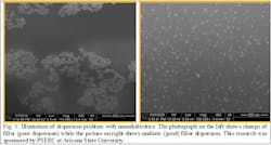
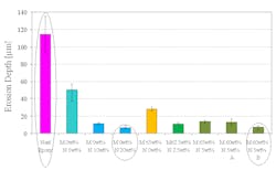
Figures 1 and 2 show the proof of concept for epoxy materials. Different amounts by weight of the base polymer of nanometer and micron-sized filler particles (silica) were mixed in the epoxy material. The samples were prepared as 1-mm thick sheets. They were subject to corona from a needle for several hours. The resulting erosion was measured using an optical (non-contact) technique. It can be seen that just 10-20% by weight of the nanofiller provided a far superior resistance to erosion than obtained by the addition of 60% of the conventional micron-sized filler. But the challenge is to ensure that the filler particles are evenly dispersed in the material. The small size of the nanoparticles causes them to strongly adhere to each other, resulting in clumps of filler. Special processing is required to obtain good or uniform filler dispersion.
There are substantial contributions that can be made on the modeling (simulation) side as well. Understanding how insulators perform under wet and contaminated conditions requires substantial, time-consuming experiments involving big laboratories. Good computational models are a great asset to power engineers. Understanding the dynamics of water flow in the presence of electric field and wind is pretty challenging. One can tailor the permittivity and conductivity of the material to optimize the size of the equipment and also enhance performance during service.
For further reading:
1. G. Iyer, R.S. Gorur and A. Krivda, “Corona resistance of epoxy nanocomposites: experimental results and modeling”, IEEE Transactions on Dielectrics and Electrical Insulation, Vol. 19, No. 1, pp. 118-125, 2012
2. J. He and R.S. Gorur, “Flashover of insulators in a wet environment”, IEEE Transactions on Dielectrics and Electrical Insulation, Vol. 24, No. 2, pp. 1038-1044, 2017


