In the electric industry, many workers are familiar with induced voltages and their potential impact on electrical work. Typically, crews are informed about other nearby power sources in the morning job brief, prior to the start of construction. Something not often discussed is that the same concept of voltage being present on supposedly dead conductors also affects railroad signaling, operation and safety.
In recent years, Commonwealth Edison Co.’s (ComEd) project and maintenance work has become more and more impacted by modern railroad induction considerations. ComEd has developed strategies to avoid or resolve conflicts between the railroad and utility.
Railroad Signaling
To understand how power lines can affect railroads, a basic understanding of railroad signaling is needed. Simple railroad signals historically used the potential (voltage) difference between the track rails to determine if trains were present at certain locations. Each track typically was broken down into 2-mile (3.2-km) sections with insulated joints maintaining electrical separation.
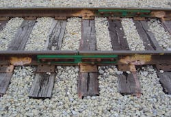
In addition to maintaining electric isolation between the sections of track, these insulated joints maintained structural integrity. In each section, a low-voltage signal (less than 10 V) was placed onto one of the two rails; traditionally, it was a direct-current (DC) voltage. The voltage between the rails then was monitored in each track section.
When a train crossed over the electric isolation (insulated joint), its wheels—which are electrically continuous—shorted the section out and the potential difference between the two rails went to zero. The railroad used this to determine a train was on a specific portion of rail and, to this day, this information is used for purposes such as controlling crossing gates.
In the modern era, railroads are moving to much more complicated signaling while still using the rails as the fundamental medium for communications. They have moved away from DC systems and now favor alternating-current (AC) frequencies to transfer their signals.
This, in coordination with expansive relays and signaling devices, makes the signals much more susceptible to power line interference, which also is AC. Making the issue even more significant is the frequencies used often approach power line frequencies (60 Hz in the United States) and their harmonics, which makes it much easier for interference to occur.
AC Induction
AC induction is an electromagnetic phenomenon where a changing magnetic field—often from power flow through nearby power lines—can cause an induced current and voltage to be present on conductors that are nearby and not actually connected to any power supply. The strength of the induced current and voltage depends on factors such as the power source distance and current.
AC electricity causes induction because of the constantly changing character of its magnetic field, as voltage changes repeatedly between positive and negative. An interesting sidenote, steady-state DC electricity cannot cause induction because its magnetic field is constant and does not change. Michael Faraday generally is credited with the discovery of induction in 1831, and James Maxwell mathematically described it as Faraday’s law of induction.
In simple terms, induction is an electric effect that potentially can cause conductors in parallel to a live AC power line to become energized. In the case of work on utility lines, this can happen when a distribution line is underbuilt on transmission structures. Disconnecting the distribution line from its source does not make it safe to work on. Additional grounding and testing must be done to ensure the above transmission wires do not induce a current into the line.
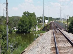
Railroads are not exempt from this scenario. Physically, railroads are composed of at least two metallic (and conductive) rails that run along their entire length. As far as electricity is concerned, these rails act as any other conductor and readily will have a current induced on them from nearby AC power sources.
As previously mentioned, the railroad uses the conductive nature of the rails for signaling. This signaling is what enables railroad crosswalk arms to come down at the right time and alerts railroad operators when a train is on a certain section of the rail. In some cases, the railroad can even monitor how fast the train is moving. Unintentionally inducing a current from power lines to the rails can disrupt the normal operation of these signals, shut down the railroad, or damage equipment until the source of the induced current is deenergized or an effective mitigation system is installed.
The effects of induction on railroads are significant enough that coordination traditionally has been part of the design process at ComEd. However, recent changes in the railroad industry, enabling more accurate AC-based signaling systems, have made railroads even more susceptible to interference from power line circuits. This vulnerability has brought to light issues not historically in the ComEd region. For example, in some locations with double-circuit lines, the utility no longer can take single circuits out of service for maintenance without risking a railroad that shares the right-of-way having to be shut down for safety. This occurs because the normal operating condition of the two circuits results in a cancellation effect that a single circuit cannot achieve.
Ways to Mitigate
Railroad interference has had impacts on recent outages in ComEd’s service territory. This has brought attention to the utility’s need for development of robust railroad induction mitigation for new installation projects and upgrades. Railroad mitigation itself is any practice or installation that reduces the maximum amount of current and voltage induced onto the railroad.
To effectively mitigate a railroad induction concern, ComEd first aims to determine the magnitude of the problem. The utility completes a railroad induction study, identifying all energy sources in the area as well as the locations of all nearby conductors and then modeling them. Once the model is complete, the utility runs an analysis of the worst-case currents and voltages that exist on the railroad. The layout of the model then can be adjusted to reflect different mitigation techniques and installations.
Mitigation for AC interference can come in many forms. One possibility is a mitigation wire, also known as counterpoise. This can be defined as any conductor, typically grounded, that is installed parallel and near to the power lines or rails—but not connected to a power source—with the intent of minimizing the effects of induction. Another possibility is extra insulated joints, which can be effective by shortening the isolated railroad signal sections and limiting the critical section lengths.
However, the option with the largest impact, is changing the electric line geometry. Factors such as distance from the railroad to the conductors and the orientation of the power line can either create or avoid a point of concern. Unfortunately, these factors cannot be changed easily because of the limited amount of land available to utilities. While upgrades or maintenance work often have a set proximity to railroads, new construction can attempt to obtain more distance between the railroad and power lines to avoid conflict.
Many other methods of mitigation exist but are less common in the industry. At ComEd, the most common mitigation designs involve overhead or underground mitigation wires. This is effective because the installation is often like traditional design methods but without connections to power sources.
Mitigation Example
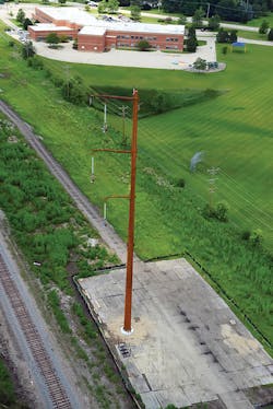
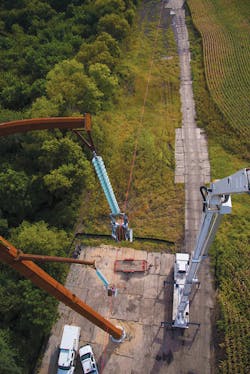
ComEd has both historic and modern experience with railroad mitigation. One of the most significant is Grand Prairie Gateway, a new 60-mile (97-km) transmission line, constructed in 2016. This 345-kV monopole line parallels railroads for nearly 10 miles (16 km). Because of this, a mitigation study was completed prior to construction and it was realized the line proximity led to railroad-induced voltages that were higher than acceptable. Mitigation was then added to the design, with some sections getting as many as six mitigation wires (four underground and two overhead) in addition to installing five insulated joints on the railroad.
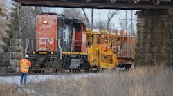
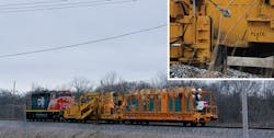
For the underground wires, the typical construction method of trenching was not deemed acceptable because of the proximity of the railroad and loadbearing nature of the ballast surrounding the rails. Instead, custom vibrational plows attached to train engines were used to complete the installation.
Close coordination with the railroad organization was critical. With only one track in the area, no other trains could use the segment of the railroad under construction. The railroad also coordinated the installation of five insulated joints to reduce further the rail voltages to acceptable levels, typically below 50 V. These nonstandard installations increased construction time and added to the project budget.
Early is Key
Completing a mitigation study early is preferred because much can be saved by designing route and structures based on the results. If mitigation is deemed necessary after completion of a design, then more costly and invasive designs will be required to create a system in coordination with the railroad.
As can be inferred from the results of the Grand Prairie Gateway design, railroad mitigation can have significant impacts to a project’s budget and timeline. Because of recent changes in railroad signaling technology, all railroads are becoming more and more susceptible to interference. If not appropriately mitigated, this interference could cause railroads to shut down and even damage their signaling equipment. In many cases, the interference also can make it difficult for the utility to obtain line outages. As the utility continues to use land next to railroads, induction studies should be completed more and more frequently to ensure the two systems can operate in harmony.
Ryan Cisko ([email protected]) is a Project Engineer in Transmission Engineering at Commonwealth Edison Co. He is a licensed professional engineer who has earned bachelor’s degrees in mechanical engineering and aerospace engineering from the Illinois Institute of Technology. His experience includes wood and steel design, North American Electric Reliability Corp. (NERC) facilities ratings, specifications development, and emergent event response. He has held key roles in multiple large-scale efforts, including the utility’s largest transmission line build in 30 years, the 60-mile (97-km), 345-kV Grand Prairie Gateway project.
