Substation Upgrades Bring Renewables Home
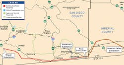
To meet the state-mandated California Renewables Portfolio Standard, San Diego Gas & Electric (SDG&E) constructed, energized and put into service a Sunrise Powerlink project connecting San Diego, California, U.S., to the renewables-rich Imperial County, California. The standard requires investor-owned utilities in California to increase procurement of renewable energy resources (RERs) to 33% by 2020.
The Sunrise Powerlink project includes approximately 117 miles (188 km) of 500-kV and 230-kV overhead and underground transmission lines with several large 230/500-kV substations. SDG&E also is in the process of upgrading its transmission network to accommodate more than 1,000 MW of wind and solar generation.
Location, Location, Location
Most of the RERs are located in isolated desert areas, away from load centers but relatively close to 500-kV and 230-kV transmission line corridors. The remote locations of RERs, extensive time required for permitting and environmental restrictions required SDG&E and RER developers to build high-voltage switching switchyards at remote locations to interconnect the new, clean generation directly into the existing 500-kV and 230-kV transmission line infrastructure.
The switchyards’ bus configuration, equipment specification and method of interception of these switchyards into the transmission grid have been carefully designed and selected to ensure a high level of transmission system reliability and operability while cost-effectively incorporating the large amounts of renewable power generation on the grid.
Ocotillo Wind
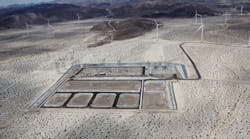
To accommodate the 265-MW Ocotillo Wind project, SDG&E looped the 500-kV transmission line into the 500-kV switchyard using a ring bus configuration with a fully redundant ac-dc auxiliary power system. The site location and ultimate arrangement of the switchyard were selected to allow future switchyard expansion to a substation with a breaker-and-a-half configuration arrangement.
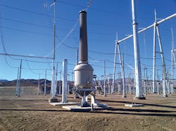
One of the challenges for SDG&E’s substation engineering team was to provide a 500-kV station service voltage transformer (SSVT) for the Ocotillo switchyard to supply auxiliary power. Based on market analysis and discussions with different manufacturers, the substation engineering team came to the conclusion to adapt a 500-kV SF6 gas-insulated instrument transformer to the specific switchyard requirements. Specified with a 333-kVA nameplate rating, the single-phase SSVT has been manufactured and passed all selected IEEE/International Electrotechnical Commission (IEC) factory acceptance tests required for gas-insulated substation equipment.
As a result of the high-reliability requirements of the switchyard, two SSVTs have been installed at different buses. Each SSVT is operated and protected by the combination of single poles of the 500-kV disconnect switch and 500-kV dead tank circuit breaker. One spare SSVT is kept on site in case of an emergency.
Solar Approach
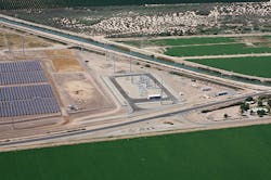
The sun shines pretty much year-round in Southern California’s Imperial Valley, which makes it an ideal place for large-scale solar energy power projects, the energy from which will ultimately need to be delivered to San Diego through the Sunrise Powerlink transmission lines. For multiple large solar projects, with total projected capacity of more than 500 MW, a 230-kV collector switchyard was built and interconnected with a short transmission line into a large 500-kV transmission substation.
With the expectation that integrating RERs into an existing 500-kV series-compensated line might change the segment lengths and corresponding level of compensation,
500-kV series capacitor banks for new 500-kV substations were designed for selectable ratings. The series capacitors were equipped with easily replaceable jumpers to change the compensation level and corresponding protective level of metal-oxide varistors (MOV). In addition to the series capacitors’ standard bypass breaker design, maintenance breakers with corresponding disconnects were installed to fully isolate the series capacitors during system faults and outages.
Penetration Levels and Integration
As penetration levels of the RERs in SDG&E’s power system increases, the dynamic characteristics of the system are changing. One issue of particular concern was the resulting reduction in system inertia and increased harmonics content. All integrated wind and solar photovoltaic (PV) power plants are power electronics-based and do not inherently contribute to the inertial response of the system, reducing the ability of the grid to reliably withstand large changes of load or losses of generation. This situation was exacerbated by the demolition 689-MW South Bay Power Plant as well as an unexpected shutdown of the 2,150-MW San Onofre Nuclear Generation Station in Southern California.
The difference in the dynamic response of the system to the same type of large shunt capacitor switching event recorded in 2006 and 2014 was apparent. It was clear that, from recordings of the event in 2014, current was distorted by harmonic components and was reacting with much harsher oscillations than the same system event in 2006.
Behavior with FACTS Devices
Another important consideration with integration of renewables into series-compensated transmission networks is the electrical behavior of wind and solar generation with additional flexible ac transmission systems (FACTS) devices required for providing power flow and voltage control of the entire power grid. Engineering, grid operation and maintenance personnel are not as familiar with these low-inertia, intermittent dc-ac power electronics-/inverter-based energy sources.
These sources can create switching overvoltages and transients on a much larger scale than for which the substation equipment was planned. This extreme electrical stress is dangerous especially to 230/500-kV apparatus traditionally designed with reduced electrical insulation protective margins. All these challenges need special attention during the design and selection of substation apparatus and components, and require advanced system studies to review equipment specifications as related to reliability, insulation coordination, transient and harmonic withstands.
Industry experience shows that when the large utility-scale solar PV arrays integrate into the transmission grid, the elevated levels of voltage distortion usually observed — even the emission level of an individual PV inverter — satisfy the power-quality (PQ) standards. Harmonics also can be an issue for the transmission and collection substations because of numerous switching capacitors at collector substations, shunt reactors at transmission substations and the existence of background harmonic distortions on the transmission network.
Constantly changing system frequency response characteristics may create resonance as more capacitors, reactors and underground cables are installed. This subsequent dangerous equipment stress could have a more significant impact than the injection of harmonics from the renewable generation themselves. Short-circuit interruption is often thought of as the most severe duty for circuit breakers. However, many interrupter technologies use the energy in the arc to generate the pressure necessary to interrupt high magnitude currents.
In contrast, capacitive and small inductive currents are quite low in magnitude compared to short-circuit currents. These small currents do not stress the thermal capabilities of the interrupter but may challenge the dielectric capabilities. The circuit breaker and its components may not be capable of withstanding the high magnitude of transient recovery voltage (TRV) across the breaker contacts. This can result in re-ignition and re-strikes with the possible consequences of breaker and connected high-voltage equipment damage.
Electrical failures of circuit breakers associated with capacitor and reactor switching, even with modern gas-insulated substation design and zero-crossing control, are perhaps the most common electrical failures at SDG&E substations.
The series compensation connected with the inductance of a transmission line can form a series resonant circuit with the natural frequency in the sub-synchronous resonance (SSR) range with the possible interaction of a natural frequency with the shaft mechanical system of nearby induction generators. Sub-synchronous control interaction (SSCI) also can be induced between a wind-generation power plant and series-compensated lines. Bigger swing currents, less mechanical inertia and low damping oscillations may drastically increase the energy dissipation requirements to substation equipment surge arresters and the maximum TRV magnitude for transmission line breakers.
Understanding the New Environment
To address these unique system conditions, SDG&E engineering initiated an integrated approach to better understand the new electrical environment and develop solutions to prevent substation equipment overstress conditions. This approach includes modeling detailed substation topologies and equipment configurations, monitoring voltage and existing harmonic distortion at the major 230/500-kV interconnection points, extending condition-based maintenance deployment to collector switchyards, and incorporating harmonic and transient alleviation technologies to reduce the possibility of substation equipment degradation and failures.
SDG&E has traditionally monitored distribution system PQ by establishing PQ nodes at select distribution substations. In late 2000, SDG&E deployed a PQ data management system that provides a web-based interface to a large database, which stores collected records. PQ data collection from transmission substations at that time was not in issue and was not installed.
As a result of the RER integration onto the transmission system, the existing distribution PQ data management system has been expanded to accommodate the new stream of the transmission system’s PQ data. The data has been collected by substation meters with PQ measuring ability, strategically located at major RER interconnections. The data shows the level of total harmonic distortions recorded at SDG&E 230/500-kV substation buses during the last few years. This data has been analyzed and used as a benchmark in the comprehensive electromagnetic transient (EMT) studies and forwarded to developers for equipment selection and specification.
Electromagnetic Transient Analysis
The SDG&E transmission network EMT model has been upgraded with detailed simulations of PV inverters, wind turbine generators and collector substation configurations based on the information provided by manufacturers and developers. The frequency scan, L-C interaction and resonance overvoltage screening simulations have been included in the insulation coordination studies, in addition to the traditional lightning and switching analyses.
Additionally, an examination was completed on individual harmonic impacts on the surge arrester’s energy dissipation, 500-kV series capacitor bank’s MOV duty ratings, 500-kV shunt reactor’s circuit breaker TRV and transformer saturations. Corresponding power flow studies were conducted, and the conclusion was that additional volt-ampere reactive and voltage-control devices — with specific inertia and transient response parameters — are required to provide voltage control and stability of the SDG&E power grid.
PSCAD software simulation results, which show TRV requirements for circuit breakers switching 500-kV shunt reactors, have been sent to the breaker manufacturer to verify breaker performance.
Looking to the Future
Current knowledge is still insufficient to ascertain the extent to which any new renewable generation will affect voltage and current power quality, or how the existing transmission grid can sustain a particular level of harmonics and continue to perform its function reliably. However, a significant experience has already been accumulated and is available to analyze current and predict future transmission system evolution and improvements.
Dr. Yakov Shlemenzon ([email protected]) is a principal engineer of the substation apparatus and standards group at San Diego Gas & Electric Co., focusing on innovative technologies application in electrical substations. He has more than 30 years of electric power engineering experience in transmission and distribution system design and analysis. He is a senior member of the IEEE, a member of CIGRÉ and a registered professional engineer.
Karl Iliev ([email protected]) has worked at San Diego Gas & Electric for more than 13 years in both transmission and distribution in roles ranging from planning to engineering to operations. He is currently the manager of substation engineering and design, where he coordinates with operational departments to improve short- and long-term system performance through substation design. Iliev has a bachelor’s degree in electrical and electronic engineering, with a concentration in power systems and a minor in physics, from California State University of Sacramento. He is a registered professional engineer.
Company mentioned:
San Diego Gas & Electric | www.sdge.com
Sidebar: Station Recommendations for Renewables
Based on equipment performance history, field recordings and system simulations, SDG&E is implementing the following recommendations:
• Avoid wind- and solar-generation sources’ direct interconnection into substation buses. Design and install 500-kV and 230-kV collector switchyards for generation interconnections and future system expansions.
• Use synchronous switching controlled 500-kV single interrupter circuit breakers to eliminate grading capacitors and other breakers’ components degradation during frequent 500-kV shunt reactor’s switching.
• Use advanced circuit switchers with transient recovery voltage (TRV) mitigation technologies for large shunt reactor’s and shunt capacitor’s daily switching requirements.
• Forward simulation results of required chopping numbers and expected TRV during 500-kV shunt reactor switching to the circuit breaker’s manufacturer for confirmation and equipment selection.
• Require the installation of high-energy dissipation surge arresters at 500-kV and 230-kV terminals on all transformers, shunt reactors, line-side circuit breakers and shunt capacitor banks.
• Energize substation autotransformer banks from the low side with shunt capacitors and reactors off-line to reduce excessive temporary overvoltages.
• Avoid simultaneous energizing of 500-kV transmission lines and autotransformer banks to limit excessive duties applied to surge arresters as a result of temporary overvoltages.
• Upgrade limited-frequency-response capacitive voltage transformers with harmonic monitoring units, which allow measurement up to the 50th harmonic (3,000 Hz).
• Use only the IEEE 693 seismic standard qualified substation equipment and apparatus with composite insulators and bushings.
• Coordinate with developers, major customers and neighboring utilities to identify the source of high-voltage harmonic distortion and develop corrective measures.
• Specify gas-insulated instrument and station service explosion-proof transformers at critical system locations.
