Quality Control in Protection & Control Design
A Protection and Control (P&C) design package for a typical substation includes a number of interrelated drawings, including one-line diagrams, schematic diagrams, wiring diagrams and interconnection diagrams, as well as numerous calculations to support the overall design. The accuracy of these drawings and calculations has long been recognized as critical to the successful, safe and secure construction, commissioning and operation of a utility substation. In this briefing paper, we want to refocus our attention on the Quality Control of the P&C design package as well as an overall Quality Control (QC) to respond to the fast-moving changes in our industry.
Industry Changes
The typical electric utility workforce, including engineers, technicians, etc., is aging and retiring at an increased rate. These experienced, knowledgeable senior-level employees are commonly being replaced with more junior staff, and so having a solid and up-to-date Quality Control Plan is important to maintaining a high level of excellence.
Engineering consultants are being used not only to develop the P&C design packages but also to act as the owners’ engineer and to carry out the utility’s Quality Control Plan, among other important engineering roles. This again demonstrates the necessity of having a solid and up-to-date Quality Control and Quality Assurance Plan.
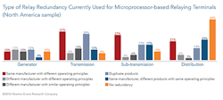
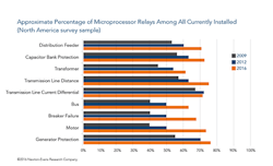
Technology changes in utility substations including the new IEC-61850 communication standard also require us to refocus on quality. These automated substation designs have changed the P&C physical designs considerably. As shown in the following graphs, the range of relay technologies and number of suppliers is rapidly growing, making well-thought-out quality plans even more critical. Some utilities now rely on extensive development and utilization of logic diagrams for these platforms. Therefore, expanding the QC to the software and supporting documentation for these platforms is also crucial.
P&C Design Standards
Having detailed and well-thought-out P&C design standards is an important element in the Quality Control Plan. The design standards are typically developed for common substation equipment (for example, line protection, transformer protection and bus protection) and include a set of standard drawings such as schematic diagrams, wiring diagrams, layout drawings and materials lists. These standard drawings can be used as a template to develop the site-specific drawings that are modified to accommodate the individual application.
The P&C design standards are part of the QC process. The checking team uses them as a tool to verify that a new design meets the utility’s requirements. Quality improvement is a big benefit of design standards, but other upsides also include consistency of designs among multiple design teams and/or consultants, improved design efficiency, and the elimination of differences strictly due to personal preferences. Design standards also can have operational and maintenance improvements by reducing the number of unique designs that operators and maintenance personnel need to work with and understand.
Peer Reviews and Point-to-Point Checks
Peer reviews and point-to-point wiring checks are the most important elements of a good Quality Control Plan.
The peer review process involves one or more competent and qualified people (in the engineering topic) to review and evaluate the design and identify any errors or omissions. A common practice is to perform a peer review of schematic diagrams for the functional accuracy of the design. This can be performed before the point-to-point wiring and interconnection diagrams are developed, therefore capturing any errors early in the design process.
Point-to-point checking is the process of verifying that all wiring points on schematic diagrams are developed accurately (and equivalent) on the wiring diagrams. Typically this is done by tracing and highlighting each circuit on each drawing. This process should be included on all design components to ensure the accuracy of the entire design package.
Checklists and Sign-off Lists
To ensure all aspects of the P&C design package are complete and accurate, meet the client’s scope of work and design standards, and have been peer-reviewed with all point-to-point wiring checks, an additional step in the QC process is required. This step is typically implemented with checklists and/or sign-off lists.
A common practice is to use a checklist of very specific tasks that must be completed as part of the process. These tasks can be technical in nature (for example, use only one ground per current transformer and voltage transformer circuit) or non-technical (for example, make sure the proper border, revision block, text size, font, blocks/cells and client CADD standards have been followed).
It is also a common practice to require a signature or the initials of the person performing the QC task. This provides a record of who performed the specific checking task and also assigns personal accountability to the QC task.
The sign-off procedure is most effective if presented in a multi-step closed-loop process as described below:
Step 1: The designer signs off, indicating the document is complete and self-checked.
Step 2: The checker signs off, indicating the peer review or checking is complete.
Step 3: The designer again signs off, indicating all checking corrections and comments have been resolved or included in the document.
Step 4: The checker again signs off, indicating all checking corrections and comments have been resolved or included in the document.
Partial examples of these documents are included below.
Industry Resources
The IEEE Power & Energy Society (PES) Power System Relaying Committee (PSRC) develops standards, guides and recommendation practices to assist the industry in applying best practices. These technical documents are essential reference information to any P&C system design. A list of these standards and guides is available on the IEEE website.
The PSRC also has developed a freely available report outlining industry practices of quality assurances for P&C design that is a good reference on this subject.
North American Electric Corporation (NERC) is also an important resource. NERC’s federally mandated mission is to ensure the reliability of the bulk power system in North America. In the course of fulfilling this obligation, NERC also provides technical information useful to the whole industry.
One very useful service provided by NERC is its lessons learned resource, which features published documents that clearly identify common problems that have been experienced, as well as the corrective actions taken, and of course the lessons learned during the process. A quick reference guide to these documents is available on the NERC website as well.
Other P&C Design Quality Control Elements
Below is a list of additional QC elements that also should be incorporated in a good Quality Control Plan:
- The role of cost, scope and schedule in the P&C design process
- Communication with the entire design team, including other engineering disciplines
- Communication with the client
- Establishing qualifications for the roles in the design and QC process
- Document control
- As-built documentation
- Monitoring and measuring the effectiveness of the QC process to provide feedback and improvement
Conclusions
The paramount goals of a Quality Control Plan are to provide high-quality P&C design packages that meet client scope and standards, without errors and omissions, and that are constructed without errors or problems. Resources available from IEEE, NERC, and the checklists and guidance provided by this document will help you to understand all the elements necessary in a Quality Control Plan to achieve this goal.
Content provided by TRC. For more information contact:
Timothy Farrar • Augusta, ME • Chief Engineer – Protection and Controls • 207.621.7027 • [email protected]
Stephen Persutti • Rocky Hill, CT• Vice President of Utility Development • 860.202.4244 • [email protected]
Stay Connected with TRC
To download a copy of this T&D World Refresher, complete the form below.


