In recent decades, the growing need for electric power has surfaced the need to implement increasingly efficient and reliable automation and protection systems for substations. The development of remote substation control and automation, which supports the remote management of a plant, also has become fundamental to the operation of the electricity network.
Substation automation systems (SAS) are the new generation of systems that perform the functions of protection, automation and control. Designed based on the functional requirements of the IEC 61850 standard, they quickly have become a key component of the transmission system. In fact, with the introduction of the IEC 61850 standard, utilities evolved from engineering the functionality in a substation with electromechanical systems to the adoption of architectures operating with standardized sets of protocols on high-speed local area networks (LANs). This step also made it possible to bring uniformity to the operation of each station, whereas previously they operated with proprietary solutions that oftentimes differed from each other. For this reason, an important benefit of IEC 61850 was laying the foundation for interoperability between devices from different suppliers.
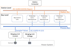
Thanks to the use of high-speed network technologies inside the substation, it was possible to develop the process bus — defined and regulated by IEC 61850-9-2 and IEC 61850-9-2LE — for the transmission of measurements to the equipment of monitoring and protection through digital protocols. The centrality of transmission networks has resulted in utilities using redundancy techniques aimed at strengthening the LANs to handle the increasing flow of information.
Today, interoperability plays an important role in the adoption of the process bus to enable communication from the merging unit (MU) to the protection units. Furthermore, using the parallel redundancy protocol (PRP) and highly available seamless redundancy (HSR) can strengthen the communication network.
Interoperability Aspects
An essential building block of a SAS, the MU acquires current and voltage signals from various transformers, converts them into digital form and sends them through the process bus, as sampled values (SV), to protection and monitoring equipment, often from different manufacturers.
In the implementation of this digital solution, the definition of a structured test process is fundamental to the following tasks:
- System integration — Testing and verifying the correctness of the configuration of the devices involved in the communication, engineering of the IEC 61850 profile and interoperability of devices from different manufacturers
- Functionality — Single-device protection setting, timing, zone-reach testing, communication testing, interlocking testing
and verification of the reaction times of the protections after fault events - Performance — Definition of performance evaluation criteria and performance in terms of
latency delay in data transmission, priority handling and single/double points of failure testing, and
interlock testing.
With regard to interoperability among the high-voltage optical sensors, MU and distance protections in the high-voltage line, an ad hoc LAN is used with two distinct sections: the process bus, in which SV is generated by the MU transit, and the station bus, for sending the information — through a generic object-oriented substation event (GOOSE) and report — to the substation server. In this context, some of the following checks are key:
- Measure verifications of the protections.
- Check on the time-synchronization system.
- Verify correctness of the data flow.
- Checking for Interoperability
Regarding the first check for interoperability, measuring verifications of the protections consists of verifying the correct behavior of the optical measurement chain (that is, the optical sensors, MU and protections, with generation of SV and, more generally, the measurement functions of the protections being tested). Some preliminary tests normally are performed in stationary conditions, with voltages and sinusoidal currents at 50 Hz constant in module and phase as well as with conditioning signals (logic inputs) constant with standard values. Each test in which no fault events occur enables a utility to verify the congruence of voltage and current measurements (and related phase-shift angles) at different levels, including short circuits.
In relation to current measurements with optical sensors, it is important to verify some fundamental results:
- Current sensors must be substantially insensitive both to the possible centering of the current conductors and to the greater or lesser uniformity of the distribution of
coils around the coils of the sensor itself. - Current sensors must not have interference between the phases.
- Values coming from the MU must be read in a congruent way by the protections of different manufacturers.
The second check for interoperability involves the time-synchronization system. Synchronization of the devices is an important aspect as defined in IEC 61850-5-2LE. However, to allow for comparison between the test results, it is equally important for the tools used in the tests, the MU and the circuits implemented with the respective technologies to be synchronized by the same source of synchronism.
The third check for interoperability is to verify correctness of the data flow. In conditions of absence of perturbations in the field measurements (rest condition), it is important to verify the communication network allows normal circulation of the SV, GOOSE and report in the dedicated network segments. Verifying the flow out of the MU complies with the IEC61850-9-2/-2-LE standard.
PRP and HSR Protocols
Communication requirements in substations are evolving to support advanced applications based on mission-critical messages, such as the execution of fast protection and control commands. In this scenario, network redundancy becomes a crucial implementation aspect and must be designed to ensure adequate recovery times for mission-critical functions in the event of a failure. In this sense, networks based on classic redundancy through rapid spanning tree protocol (RSTP) may not provide transmission reliability.
IEC 62439-3 responds to this need by defining two protocols that provide near zero recovery time: PRP and HSR.
For most communications in substations — such as that between field devices and station supervisory control and data acquisition (SCADA) — a recovery time of hundreds of milliseconds is adequate, while for messages — for example, lock or unlock, based on GOOSE or SV messages — this time is high. A mission-critical message must be received within the time limits of a milliseconds interval, otherwise the protection functions would be compromised.
The goal of implementing a redundant network is to ensure timely packet delivery for various applications. The IEC 62439-4 standard defines PRP and the IEC 62439-5 standard defines HSR—both with a 0-msec fail-over time, as required by critical high-speed functions with no packet loss. Two independent network interfaces present on a single device transmit the same data at the same time. The redundancy monitoring protocol ensures the recipient uses only the first data packet and discards the second.
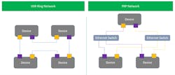
The concept of PRP is based on the dispatch of two copies of each frame on two redundant hardware paths that also can be different in terms of performance and topology. PRP is implemented in end devices, and switches on the network use standard Ethernet. The PRP unit sends a message to the network through both ports at the same time, with the message passing through the two independent networks to the PRP unit. The unit manages the first packet and discards the second.
Unlike PRP, HSR is designed for use in ring topologies. The basic principle is to send identical frames in both directions around a ring. This ensures a copy of the message will arrive at its destination, even if the ring is broken. Using two network ports, an HSR connection incorporates a double node that connects the two interfaces to form a ring. Each HSR node receives all frames that are sent only to it. Multicast and broadcast messages are relayed by every node in the ring. To prevent these messages from circulating forever, the HSR node that initially sends the message over the ring will remove it when it returns to the node.
In the case of a failure, a frame is sent by using the network in operation. In this way, there is redundancy with zero switchover time.
Process bus and LAN redundancy protocols are primary solutions to the evolution of digital technology in next-generation electrical substations. The challenge that awaits transmission system operators (TSOs) now is implementing such solutions, fully exploiting their potential and ensuring complete interoperability between the devices involved. This can be achieved only through proper design and testing processes.
Aldo Curtoni is a senior consultant in the field of operation technologies with CESI SpA, headquartered in Milan, Italy, and with facilities in the Netherlands, Germany, Czech Republic, United Arab Emirates, Brazil, Chile and USA. With a master’s degree in telecommunications engineering, Curtoni specializes in substation automation systems, SCADA and energy management systems, communication protocols like IEC 61850, IEC 60870-5-104/101/103, IEC37.118, and control and monitoring systems at the generation, transmission and distribution levels.
Marco Catalfamo is an expert consultant in the Energy, Industry & Electronics, Life Sciences (EILIS) division of Capgemini Engineering, with over twenty years of extensive and progressive professional experience in the electric power industry. In-depth knowledge of all stages of project life cycles, Catalfamo is highly skilled in SCADA and energy management systems, distribution control systems, remote control systems, integration of heterogeneous complex systems and communication protocols like IEC 60870-5-101/103/104, IEC 61850, Modbus and open platform communications (OPC).


