Lattice Tower Deflection: An Exception to the Rule
Traditional practice dictates potential deflection of lattice steel towers will not cause structural issues while stringing conductor. However, Los Angeles Department of Water & Power (LADWP) and Black & Veatch recently discovered an exception when the deflection of an existing tower during stringing was enough to impact stringing sequencing. The project in question was part of the LADWP’s Barren Ridge renewable transmission project (BRRTP), built to expand power-delivery capabilities to the Los Angeles basin. Black & Veatch was contracted to provide engineering design, joining the Barnard Construction (BCCI) team.
The project included the installation of two new transmission lines between the Barren Ridge and Haskell switching stations and the Haskell-Rinaldi reconductor, which included a 15-mile (24-km) optical ground wire installation and 3.5 miles (5.6 km) of reconductor.
Project Overview
Originally constructed in the 1950s, the Haskell-Rinaldi transmission line was modeled from an existing light detection and ranging (LiDAR) survey in the PLS-CADD suite of software, which was used to perform loading and electrical clearance checks. Black & Veatch compared the modeled lattice tower loads to the original tower point load design. This led to the creation of creating new tower models. Later, Black & Veatch incorporated the finite element (FE) models and performed a new LiDAR survey to incorporate current line operating factors into the model, as well.
Twenty-five conductor options using the FE models were compared to determine the effects on the lattice towers and any required reinforcements. The selection study accounted for any reinforcements required as a result of new conductor loads, giving a true comparison of the cost of each conductor option. The end-result design needed to support a larger conductor and uphold present clearance requirements.
LADWP decided to replace its existing 954-kcmil aluminum conductor steel-reinforced (ACSR) Cardinal conductor with a 2312-kcmil aluminum conductor, aluminum clad steel-supported (ACSS/AW) Thrasher conductor, produced by Jiangsu Zhongtian Technology Co. Ltd. (ZTT), because of its reliability and capacity. The design for the new line had to allow for a 50% expansion in conductor diameter and doubling of the weight per foot. Modeling software also was used to determine lattice tower and foundation modifications that would be efficient, buildable and manageable within the project schedule.
Lattice Tower 116
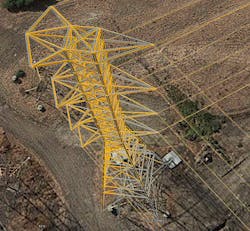
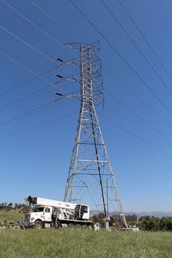
Most of the lattice towers had no or very little light line angles. However, lattice tower 116 had a line angle of 98.6 degrees. The initial line route from the 1950s had this tower as a tangent, but the development of an adjacent substation in the 1960s required the tower be replaced and the line redirected at a drastic angle. In the half century since then, lattice tower 116 had maintained tension and supported two 230-kV lines, but the new conductor’s increased load mandated upgrades to both the lattice steel and foundations.
Because force is distributed through the lattice structures, from the cable attachment points through the legs, the tower was strengthened drastically by replacing a modest amount of lattice steel with a higher gauge and strength. These discrete sections were determined by identifying members most used in different conditions and understanding the symmetry of load development (each member has a roughly symmetrical mate that, within standard use, is in alternating states of tension or compression with the other). Members were replaced in pairs to guarantee balanced load development.
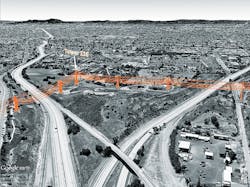
Unlike the simple replacement of lattice steel, tower 116’s construction was more complicated. It spanned Interstate 5 on one side and Interstate 405 on the other, two major freeways heading to and from Los Angeles, California, U.S. Reconductoring was done over two nights to minimize disruption while working over the busy roadways. The conductors were required to be fully pressed before traffic control could be released on each interstate.
The span from structure 115 to 116 was strung and tensioned on night one, at a tension approximately 3000 lb per phase (1361 kg) higher than the previous conductor, because of the increased size of the new conductor. Sag levels were confirmed by the Wasatch Electric Inc. (WEI) construction team, who carried out the project one phase at a time. Per standard industry practice, the conductor was installed, sagged and brought up in hoists one phase at a time. This procedure went from the top phase to the bottom phase, after which all the dead ends were pressed in their final locations at the same time.
Sag was verified for each phase by the construction crew’s surveyor as crews brought them up to tension. A quality assurance test after the third phase revealed, while the bottom phase was acceptable, the top and middle had excessive sag. Both phases were adjusted and after successful measurement, the conductor was secured in the dead-end assemblies.
The next night, WEI crews continued to string on the other side of the tower with an identical process. Once again, quality assurance testing identified some issues the crew was able to correct on-site. Installation was completed and tower 116 finished, or so crews thought.
The quality assurance surveyor returned to the site the following day to obtain additional pictures for the final report on the construction activities. However, an issue was discovered with the spans of tower 116: The tension in the back span was drastically higher than expected, while the tension in the ahead span was lower than expected. Triple-confirmed measurements revealed discrepancies with both the surveyor’s previous measurements as well as the crew’s measurements. The conclusion was tower 116 had shifted, causing the tolerance issues.
Deflection and Analysis
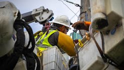
Survey results indicated the tower deflection was substantial, and the entire team went to work to get to the bottom of the issue. Engineers inspected the lattice towers using bucket trucks, looking for evidence of structural issues, but found the movement did not cause any deflection or bolt-hole deformation.
Lattice towers typically are modeled statically. It usually is an accurate description of their behavior, and to model an entire line any differently would be an excessive burden on even a modern computer’s processor. With PLS-CADD SAPS level 4 analysis, lattice steel can be modeled to behave as a system, with the movement of one lattice member or structure affecting its neighbors. This modeling helped the team to analyze the impact of stringing on the tower movement and load development as well as predict actual deflection levels at insulator attachment points.
Using FE modeling software, the team re-created the model, following each step of the process from the beginning to end of construction. This showed preconstruction tensions and the sharp angle of the line could cause the lattice tower to deflect approximately 9 inches (229 mm) into the bisector. The sequence in construction increased this deflection and added rotation.
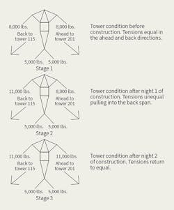
By following this root-cause analysis procedure, the design team determined, during the first night of construction, the tower deflected back toward tower 115 as the phases were brought to tension. The deflection increased as the crews brought each successive phase to tension, which is why—once all three were at full tension—the middle and top phases appeared to sag too much. The initial night of construction also introduced a rotation on the tower.
As the second night of construction proceeded, the ahead span was brought to tension. As the model showed, the tower was pulled into the ahead span as the conductor toward tower #201 was sagged at full tension. This reduced the rotation seen on the tower from the previous night; however, it increased the tension on the back span.
Deflection and sagging present in the FE model matched closely with conditions discovered in on-site surveys, giving the team confidence in the model’s behavior. Using the model and collected field data, the team determined the cable load was acceptable for the tower, but the rotation proved problematic. Caused by unbalanced loads, it would keep the tower from transferring loads between members in an efficient manner. To keep from rotating, it needed to be loaded evenly and simultaneously.
The Solution
The project’s unique constraints—a short construction timeline, stringing difficulties and permitting requirements to string over freeways—forced the team to create a solution that did not require restringing on either side. The ultimate plan was to unload both sides of the tower and bring all phases up to tension symmetrically.
To do this, a hoist was used on each attachment point to relieve most of the tension. When the outside circuit was almost completely unloaded, the lattice tower’s rotation settled to 0 degrees, with only a small deflection into the bisector. This deflection had been expected based on the modeling and was a result of the decades of tension on the tower pulling into the angle. Each phase was reloaded one at a time, lowest to highest. But, unlike the last time, both spans were sagged at the same time. Two surveyors worked simultaneously, one confirming sag tolerance while the other ensured there was no rotation, until each of the six conductors was sagged.
Because the conductor was already pressed in the dead ends, the length could not be adjusted and the existing tower attachment plates prevented any meaningful modification. Black & Veatch engineers designed custom vangs for five positions. Designers had to be precise as the margin for error was tiny, because of the tower’s proximity to its neighbors. A minor difference in conductor length could translate to a major difference in vertical sag. The vangs in the span toward tower 115 were modeled to be a full C channel to meet strength requirements while extending the attachment point into the back span. Adjusting the attachment points in the span toward tower 201 necessitated moving them closer into the tower, thus elongating the span.
The engineering team designed a new attachment plate that elongated the span just enough by adjusting the wire out of line, as it could not simply be pulled straight back into the tower. Once design and calculations were completed by the engineering team, WEI crews along with BCCI skillfully installed the new conductor attachment plates and found the vertical position change of the cable between the modeled vangs and the actual built vangs was 0.2 inches (5 mm)—well within the margin of construction and design.
The Lesson
The example of tower 116 shows, counter to common assumptions, steel lattice towers are not always unmoving structures. It is critical design engineers look at unique loading situations when planning any rebuilds, reconductors or work on existing structures. Special consideration should be given to towers with unusual load development or sharp angles, noting any unbalanced tensions during the stringing process. FE modeling can help designers to identify and mitigate any potential issues, saving time and cost.
