Power transmission and distribution (T&D) systems depend on long chains of transmission lines, substations, transformers, breakers, feeder circuits, reclosers, sectionalizers, fuses, cut-outs, service transformers, and service drops scattered over a wide geographical area. All must function systematically for the utility to deliver reliable power to its customers. Failure in the infrastructure leads to deregulated power supply until service is restored.
In an era where power has become a basic necessity, it becomes essential for utilities to strengthen their infrastructure for accommodating changes posed by deregulation and transfer reliable power to consumers. Modern power T&D systems can be categorized into two levels of hierarchy, based on the function of that particular part of the power system under a deregulated structure. In terms of the new deregulated industry paradigm, these are most easily distinguished as the wholesale level (top level) and the retail level (bottom level).
Retail sale of electric energy involves the delivery of power in ready-to-use form to the final consumers. Whether marketed by a local utility, load aggregator, or direct power retailer, this electric power must flow through the power supply chain locally on its way from power producer to consumer. Pressure on the existing network to transfer more power has led to transmission line congestion. These issues could be addressed by uprating as it allows considerable increase in power transfer capability within the existing infrastructure. It is troublesome because shut down is required for reconductoring since these lines are invariably overloaded. The primary concern in emergency restoration is to revive the transmission network, and get the line charged and back into operation within the stipulated time frame. These are the key objectives that compelled the development of an emergency restoration structure (ERS).
Common Issues of the Power Delivery Sector
The energy sector faces significant challenges as a result of aging infrastructure, including supply, security and reliability, and resiliency issues in terms of severe weather events. All of these pose a threat to public safety and the national economy. Aging energy generation and T&D infrastructure turn out to be one of the biggest challenges faced by utilities in developed and developing countries. It has a huge impact on their ability to provide a reliable, cost-effective, and ‘future proof’ provision for end users. Many countries are facing huge costs associated with electricity disruptions and customer minutes lost (CML). To avoid the cost of catastrophic failure caused by aging assets, maintenance should be prioritized.
A larger conventional conductor imposing greater loads on the existing structures may reduce the reliability of the existing line, unless the structures are reinforced. Increasing the thermal rating of an existing line by using a replacement conductor having nearly the same diameter as the original conductor but capable of operation at higher temperatures (with lesser sag and existing ground clearance and loss-of-strength constraints), may avoid the need for extensive reinforcement of suspension structures. GIS has been effectively used in the electric utility industry as an advanced mapping tool for marketing, planning, as well as operational purposes. GIS applications have also been used to control and forecast power outages. At present, these T&D lines are functioning but performing inefficiently because of aging. Ubiquitous and affordable availability of drones has added to the effectiveness of GIS applications. Replacement of old lines is required to reduce losses and achieve demand targets. The key challenges faced are as follows:
- T&D congestion
- Fewer private players
- Low investments
- Absence of strategic planning
- Renewable energy integration
Application of ERS for Line Uprating
Growing demand for electricity and an increased rate of industrialization in developing countries drive the growth of the electricity transmission market. Aging infrastructure and increasing rate of bulk power transmission across long distances drive growth of the electricity transmission towers market. Varying steel prices, availability of steel, and import and export restrictions may impact the electricity transmission towers market. The ERS installation process is being optimized to overcome site challenges, and reduce labor effort with rigorous installation and minutely observing the safety parameter as well enhancing the speed of the process. Significant features of the ERS have been briefed as below:
- Erection is very quick because of modular and interchangeable sections.
- Minimum numbers of component and identical fittings to reduce identification and segregation processes.
- Quick installation with minimum power interruption and cost-effectiveness.
- No need of special foundation or tools.
- Erection is possible in any kind of soil and terrain.
- Compatible with 66-kV to 765-kV stringing.
Reconductoring Using ERS
The complete solutions for line restoration or construction of any kind of bypass line by using the ERS tower on rental or end-to-end services can be provided in a significantly lesser time. Following are the steps for reconductoring using ERS:
Step-1: Analysis and planning: The initial step involves survey of the installation site. Pre-analysis is done of the online application of GIS which helps in estimation of a budget for the project before site visit. This is followed by the site visit which includes information such as accessibility to the site, existing tower to ERS tower clearance, right-of-way (RoW) clearance, layout of the site, span length, and so forth. Site accessibility also helps pre-determine the anchor to be used for the type of soil as well as the kind of tools. After the examination process and collection of all the details, the project engineers proceed toward the next step. The load assessment is done by the design team as per the site condition and feasibility.
Step-2: Supply chain: The second step involves bill-of-quantities (BoQ) preparation, procurement and material transportation such as the modular sections, and all the equipment required for the proper guying and installation of the tower.
Step-3: Installation and anchoring: The third step involves the installation. The major advantage of our ERS towers is that civil foundation is not required. The tower is entirely supported using guy wires. Hence, it is essential that all the guy wires are properly anchored to the soil and tension is adjusted as per the load requirement. Our team took this as a challenge and developed different kinds of anchors that would support the structure for different soil conditions. After installation of the ERS base, the gimbal joint is locked with the turnbuckle to it and with its help, a modular section is installed. Gin poles are used for lifting the next modular sections one by one.
Step-4: Stringing: For stabilizing the tower from lateral and transverse loading, a guy wire arrangement is used and anchored to the ground with required tension. All the hardware is installed along with insulated cross-arm and conductor stringing accessories. Stringing of the conductor — mostly tension type — is done with required clearance check. Additional guy wires are removed because of the longitudinal load developed with conductor stringing.
Step-5: Commissioning: Inspection and joint commissioning are conducted, electrical and mechanical safety parameter are reports are submitted followed by the charging of the line.
Step-6: Operation and maintenance: This is one of the key parts of the ERS as it is subjected to observation and rectification if required. The operation contributes to a very low ratio of ERS project expense but is vital. The operation teams are on standby until the ERS is dismantled. Deployment of remote data monitoring applications for the site offers a deep insight into the site and conditions of the tower. This helps build and develop a more robust ERS system.
Proof of Concept
Case Study: 132-kV Line, Vaishali to Sahibabad
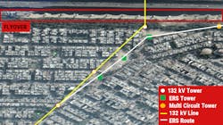
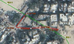
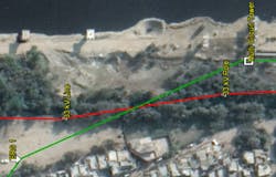
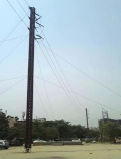
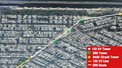
A case came to us from Uttar Pradesh Power Transmission Corp. Ltd. to shift a 132-kV line and construct a multi circuit tower replacing the existing 132-kV tower. We were also required to uprate the line by changing the conductor from ACSR to ACCC. We faced several challenges while execution of this project. Stringing was challenging as the line had a flyover and a highway crossing (as shown in Fig. 1-3).
Project Milestones
- Line crossing: 11 kV and 33 kV lines were crossing the ERS route. Needed shutdown for stringing.
- Delay in shutdown: Even after installing the ERS, re-tapping was frenetic because shutdown required for two hours from UPPTCL was difficult.
- No heavy machinery: No heavy machinery or earth movers were introduced for execution of the above, other than for transportation, which depicts the agility of the system.
- Hailstorm: There was a severe hailstorm but the tower withstood the same without any damage.. The operation of ERS can be concluded as reliable.
Evaluating Achievements and Impacts of the 132-kV UPPTCL Project
Without the ERS, this prolonged outage would have resulted in a serious economic loss to the utility. The ERS has successfully solved the uprating case of the utility. Three ERS towers were installed as shown without making any disruption to the highway traffic. The project of restoration of power using the ERS was executed in four days with a line shutdown of only four hours (as shown in Fig. 4 & 5). This exercise helped in completing a project which would evacuate 580-MW lines where substantial investment had already been made on 98% stretch of the line and the associated substation would have remained idle for an indefinite period.
Conclusion
A robust power delivery infrastructure is needed to ensure 24X7 power to all. In this context, an attempt has been made to review the relevant aspects related to optimal economic planning of aging transmission lines. This article focuses on the emergency restoration technique that can be used in case of any line reconductoring or rerouting. The steel based ERS structure was developed for the first time in India for the emergency restoration of towers. It can be erected in a few hours and is being used for up to 765-kV transmission lines across India. Its portable nature and ease of transportation makes it adaptable for wide applications even outside India. The tower designed doesn’t need foundations and is supported with guyed wire for lateral and transverse loadings. It can be oriented in any direction with the transmission lines. However, Lindsey, Tower Solutions, SBB, and DNV-GL are also providing modular restoration towers used for emergency restoration of high voltage transmission lines.
Acknowledgement
Authors thank Pradip Barua (GM Electotechnical), Arup Das (site engineer), and Prakash Reddy K. (senior manager, Planning, Production and Design co-ordination, TLT) of Supreme & Co. for their active contribution in drafting this article.
