Maximizing Right-of-Way (ROW) Utilization With Aerial Covered Conductor
Distribution and transmission planners have been besieged recently with pressing and often conflicting demands to expand the nation’s electrical grid infrastructure. With increases in renewable power generation (wind and solar) planned to grow by 42% by 2050, new transmission lines are required to bring bulk power back to load centers where that power is consumed, usually quite far from the generation sources. There is demand for new lines due to shifting demographics, as consumers move from New England and California to areas like Florida and Arizona. The industry has been talking for years about powering new, innovative load centers for electric vehicle (EV) charging centers along the nation’s highways. There is a need for system hardening in the face of severe storms, whether those lines are in areas purportedly affected by climate change, or due to the fact that humans have increasingly been moving into predominantly storm affected areas that were sparsely inhabited decades ago. Add to this the growing desire for powerline wildfire mitigation and environmental stewardship (protecting the flora and fauna). Complicating efforts to meet requirements, the American Society of Civil Engineers latest report on electric grid infrastructure identified a $200 billion funding shortfall which needs to be made up to achieve goals of reliability and resiliency for the electric grid.
Before stating how covered conductor can help, we’ll start by defining it. Covered conductor uses the same aluminum (AAC, AAAC, and ACSR) and copper conductors as bare wire construction. However, on top of the bare wire a 3-layer covering is added. The covering includes a thin semiconductor layer (to smooth out electric fields when in contact with a grounded object, minimize partial discharge, and boost the BIL) directly over the bare wire, an inner layer of low-density polyethylene (which provides a high BIL and is soft to enable stripping for taps, transitions, and line extensions), and an outer layer of high density polyethylene (providing UV inhibition, track resistance, abrasion resistance, and color). The total thickness of the three layers depends on the voltage class, as the design objective is to limit the available surface current should the phase conductor come into contact with a tree or other grounded object. While the outer two layers provide excellent insulation, NESC 230D defines them as “Covered” rather than “Insulated” conductors since there is no shield (concentric neutral).
Covered conductor systems come in two configurations. Spacer Cable Systems utilize three heavily covered conductors (usually AAC since there is no mechanical tension in the phases) supported by a high strength messenger wire and hung by polyethylene spacers every 30 feet. A Tree Wire system, on the other hand, looks more like bare wire construction. These systems utilize the same 3-layer covered conductor design, but the phase conductors are usually either ACSR or AAAC (since Tree Wire is fully self-supported and tensioned). This configuration is strung in an open wire configuration on crossarms with polyethylene insulators.
To meet the needs of new powerline construction, ROWs for new powerlines are required. Options here are limited, and fall to either obtaining a new ROW, or expanding an existing ROW, if a desirable route is available.
The problem with obtaining new ROWs is that it takes time. By the time one finishes the feasibility study, permits are granted, easements are purchased, surveys are completed, land clearing is finished, procurement, construction, and commissioning is done, it can take seven years at the least, and more typically thirteen years. We currently have approximately 1,000 GW of clean energy projects in uncertainty due to the lack of transmission infrastructure. Compare the 7-13 year new ROW project timeline to the possibility of building a new line on an existing ROW, which can be achieved in as little as two to three years, and the attractiveness of compact line construction using covered conductor becomes immediately obvious.
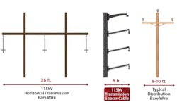
The ability to add a new distribution or transmission line to an existing ROW is further facilitated by using spacer cable, due to its reduced footprint. As an example, if we compare a bare wire 115 kV line built in a horizontal construction design, the horizontal footprint (prior to calculating blowout) is around 26 feet. If we compare that to 115 kV spacer cable, the horizontal footprint requires only about eight feet. Spacer Cable not only reduces the profile by a full 18 feet, it has the footprint of a typical 15 kV construction.
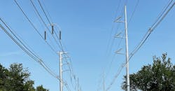
One utility that took advantage of this line compaction was able to double the bulk capacity of an existing ROW by building a new 115 kV spacer cable line with a 15 kV spacer cable underbuild. The photo below shows this project, with the spacer cable line on the left under construction.
The advantages of using transmission and distribution Spacer Cable Systems in existing ROWs include not only their compact footprint, but also: improved reliability, vastly reduced tree trimming, improved power quality (better voltage regulation and power factor), system hardening (including wildfire mitigation), ease of multiple circuit construction, improved economics, environmental stewardship (protection of flora and fauna), and a reduced carbon footprint (every tree saved absorbs carbon dioxide, produces oxygen, and makes the environment cleaner).
As infrastructure needs continue to mount, legacy systems march towards obsolescence, and timelines contract. Utilities are looking at new, quicker, safer, less costly, and more environmentally friendly ways to achieve their infrastructure goals. Aerial Spacer Cable systems provide a viable alternative to help attain this goal.
Sponsored by:
