Self-Healing Networks Come to the Netherlands
Economic growth and an increasing population translate into an increasing demand for energy. This situation, coupled with strict regulations on the quality and security of supply, increases pressure on distribution network operators (DNOs) to maintain the integrity of the network. While huge investments are already being made in replacing aging infrastructure to minimize the probability of equipment failure, the chances of failure cannot be completely eliminated. Therefore, when network faults occur, it is necessary for DNOs to minimize the impact by reducing the outage time and number of customers without supply.
To minimize the fault outage time, the Dutch DNO Stedin has started a project to introduce automation to its distribution network. The first phase of the project consists of installing intelligent fault passage indicators, while the next two phases use more advanced techniques such as remote-controlled ring main units (RMUs) and a completely self-healing distribution feeder.
Pilot Project
In the Netherlands, the distribution network consists of underground cables, which means permanent faults can occur that cannot be resolved by stand-alone automatic reclosers. Stedin developed a self-healing network pilot based on a software restoration routine that employs several remote terminal units (RTUs). The RTUs communicate through a general packet radio service (GPRS) network to identify the fault location, isolate and restore (FLIR) supplies in steps automatically.
Automatic FLIR schemes can be implemented with several different architectures. A fully centralized architecture uses a distribution management system (DMS) that has a complete picture of the network topology. Local, centralized architecture uses intelligent master controllers, each of which communicates with a limited number of slave devices.
The architecture installed by Stedin is fully decentralized, where the intelligence is distributed between several nodes. The FLIR algorithm uses messages passed between numbers of RTUs. Therefore, the communications architecture mirrors the electrical network, which makes it easy to add and remove nodes.
Automated Network
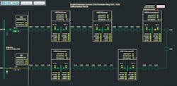
For the Stedin self-healing distribution network pilot, a medium-voltage (23-kV) network in Rotterdam’s city center was selected. This network comprises 33 23-kV secondary substations connected in an underground cable ring operated as two radial feeders by creating a normal open point.
Ideally, all 33 secondary substations would be fitted with automatic switchgear, but this is an expensive option. The cost-effective solution was to select five secondary substations and divide the ring into two feeders, each with three sections and each with approximately equal cable lengths and number of connected customers.
The five secondary substations all are equipped with the following distribution automation equipment:
- Motor drive to operate the load break switches
- RTU in which the logic is programmed
- Fault passage indicators
- Voltage presence detection.
- The 23-kV circuit breakers (V502 and V503) in the source primary substation are automated with different equipment:
- Protection relay to trip the circuit breaker
- Supervisory control and data acquisition RTU for monitoring and control
- Self-healing RTU, a smart controller, to initiate the FLIR sequence and reclose the breaker.
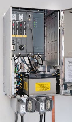
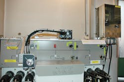
The self-healing cabinet box is equipped with the RTU, including a battery and a GPRS modem for communication purposes. The fault passage status is calculated within the RTU using a current measurement on the incoming and outgoing cables. Finally, a voltage presence indicator is connected capacitively to each cable to detect whether the cable is energized.
This pilot project has been undertaken in cooperation with Schneider Electric, developer of the T200i platform, an off-the-shelf RTU suitable for feeder automation. The T200i RTU was installed in Stedin’s self-healing network pilot. For this particular pilot project, Schneider Electric also developed the software necessary to create the self-healing algorithm that runs on the RTUs.
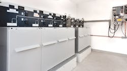
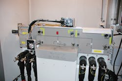
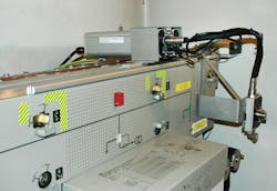
All of the automated secondary substations consist of a RM6 Type RMU from Schneider Electric and are equipped with Schneider Electric motor drives. The RMUs located in the network open point are of a different type and are equipped with a LINAK generic motor drive. The LINAK motor drives can be adapted in such a way that they can be fitted to almost every type of RMU.
Self-Healing Network
The purpose of the self-healing network is to automate the manual fault-restoration procedure. The self-healing system will rapidly restore two out of three feeder sections and the connected customers automatically, leaving one feeder section isolated. Finding the location of the actual fault within the isolated section and restoring supply to the remaining customers are performed using the traditional manual process.
The self-healing system is able to identify cable faults as well as bus bar faults in the RMU. In case of two simultaneous faults, the self-healing system is able to restore some of the power supplies.
There are two main principles for the fault location and isolation algorithm:
- If the fault detectors indicate the fault is located between two nodes, this is due to a cable fault, and the medium-voltage switches are opened in both nodes.
- If the fault detectors indicate the fault is located within a node, then this is probably due to a fault in a cable box on the RMU. In this case, opening switches within the node will not guarantee the fault is isolated. Therefore, the system opens (or leaves open) switches in the two neighboring nodes.
The algorithm also has to take into account other features:
- Safety. When any node is put in local mode, the self-healing scheme is automatically disabled at all the other nodes.
- Robustness. If a switch fails to isolate a fault, then the system will try the next switch.
- Fault tolerance. This is the ability to handle missing fault-passage indications.
Node Definition
In the normal restoration procedure, the faulted cable section is isolated by opening two load-break switches. The healthy sections are re-energized by closing the normally open point or the circuit breaker. This has led to the definition of a two types of nodes, namely breaking nodes and making nodes.
The breaking nodes are used for isolating the faulted component, while the making nodes are used for re-energizing the medium-voltage network. The controllers at each location are configured with the appropriate node definitions.
Fault Location and Isolation Algorithm
The sequence is started when a controller at the source primary substation detects operation of the protection relay. The algorithm works in two phases. Phase 1 is the upstream isolation phase: Each node analyzes whether the fault is located upstream of itself and, if necessary, isolates it. Phase 2 is the downstream isolation phase: Each node analyzes whether the fault is located downstream of itself and, if necessary, isolates it.
Operation of Phases
During phase 1, messages are sent downstream from the feeder circuit node, from the breaking node to the making node. As each breaking node receives a message, it analyzes its own local fault-passage indicators to find out whether the fault is upstream of itself. If so, it will open one of its switches to isolate itself from the fault.
If a breaking node successfully isolates the fault, then it will forward the message to the making node with the status “fault upstream and isolated.” If this status is received by the making node, it will close the normally open switch.
During phase 2, a second set of messages are sent upstream from the making node to the breaking nodes and back to the feeder’s circuit breaker making node. During this phase, each breaking node will complete its analysis of whether the fault is downstream of itself. If so, then it will open a switch to isolate on the upstream side of the fault.
If a breaking node successfully isolates the fault, then it will forward the message to the feeder’s circuit breaker making node with the status “fault downstream and isolated.” When this status is received by the feeder’s circuit breaker making node, it will reclose the circuit breaker.
At the end of each operational cycle, only the isolated will remain de-energized. The status of each controllable node is sent to the control center, which can send a repair crew directly to the isolated feeder section to locate the faulted cable.
The complete operational cycle of the self-healing network takes about one minute depending on the number of switching operations required and the speed of the load break switch. Hence, the majority of the connected customers experience a power outage of one minute. This is a large improvement in the average outage time of approximately two hours.
Lessons Learned
Started in October 2011, Stedin’s self-healing network pilot project was completed and fully commissioned in June 2012. Since the self-healing network has been in service, no faults have occurred on this automated feeder network. So, in addition to not having practical experience in the automated feeder restoration, data on the anticipated reduction in customer minutes lost is not available.
The GPRS communications system used for the project was designed as a telephone network, so it also can be used to transmit data. However, the system gives quality of service to phone calls, which can adversely affect the availability of the communications network for self-healing applications. Also, as an energy-saving practice, the telecom provider switches off some antenna sites at night, which can impact signal reception at some automated substations. These issues need to be addressed during the planning phase of the communications infrastructure for self-healing grids.
The majority of the downtime of the self-healing network is caused by the modem reset invoked by the telecom provider. The telecom provider resets all unused connections daily, which results in a restart of the RTU modems. During this reset, the self-healing network is unavailable for two minutes.
In general, for future developments of smart grid applications, greater attention has to be given to the performance of the telecom network. Stedin anticipates the telecom providers will adapt the performance of these types of networks by introducing different data contracts to make the network suitable for these types of applications.
Network Design
Not all medium-voltage networks are suitable for self-healing systems. In meshed networks, various possibilities are available to restore the network following a fault. This complicates the software routines and chances of malfunctioning increases. Therefore, to maximize the benefits of distribution automation, the automation functions should be incorporated in future distribution network design. This means the ring structure with a single normal open point is preferred for self-healing network functionality. Currently in the Stedin service area, the design of the distribution networks is not ring-based networks.
Future Developments
Stedin has started a second self-healing network project that is not based on a fully decentralized architecture but rather on a regional controller located in the source primary substation with a number of local control units placed in the secondary substations. Also in this project, the GPRS network is used for communications between the regional controller and local control units.
The core of the system is the regional controller where the self-healing algorithm runs and identifies all the restoration switching decisions. The local control units execute these switching actions and provide the regional control unit with an actual process image of network status.
Stedin also has started the implementation of a DMS in its control center. This system also can be equipped with self-healing algorithms, and Stedin plans to explore all of the functional features of this system.
All projects are subject to a 12-month trial period, after which all projects will be evaluated. Stedin will then be well positioned to decide on the design of future distribution networks, the self-healing algorithms required and the new technologies to be installed to improve the reliability of supply.
Acknowledgement
The authors wish to thank Dr. Tom Berry from Schneider Electric for his close cooperation, which made this project a success.
Edward Coster ([email protected]) was awarded a BSEE degree from TH Rijswijk in 1997 and a MSEE degree from Delft University of Technology in 2000. He joined Stedin in 2000 as a senior specialist for network planning. In 2006, Coster joined the electrical power system group at Eindhoven University of Technology on a part-time basis to start a Ph.D. research project, which he obtained in 2010. His main fields of interest include distributed generation, power system protection, distribution automation, dynamic behavior and stability of power systems.
Wim Kerstens ([email protected]) is an expert in asset management with Stedin. He holds a BSEE degree in electrical engineering and has 33 years of utility experience with supervisory control and data acquisition and energy management systems and information technology. Kerstens is a member of the Dutch NEC 57 Committee and of the Dutch Data Information Infrastructure Platform (Netbeheer Nederland). For the past five years, he has been responsible for the development of the Stedin technical concept for substation automation systems based on IEC 61850 standards and the rollout of these kinds of systems in the primary substations.
Companies mentioned:
LINAK | www.linak.com
Schneider Electric | www.schneider-electric.com
Stedin | www.stedin.net
