Utility Reduces Risk of Explosion
The explosion of a current transformer (CT) can cause serious damage to equipment in close proximity, but the potential risk to human life during an explosion and the aftermath is an even greater concern. In an explosion caused by overstressed dielectric or hydrogen generated by partial discharge activity, for example, the ceramic parts of the external insulator are blown to bits, scattering debris across an area of up to 200 m (650 ft).
Although the number of CT explosions is small, the effects of explosions can be immense, especially when human lives are at stake. The Israel Electric Corp. (IEC) launched a research project to find a simple and effective means to prevent this phenomenon.
Partial Discharge Activity
In normal operation, the secondary winding of the CT must remain closed through a burden circuit, or short circuit. The leads of the secondary winding may only be opened during an inter-turn overvoltage test. The test current at system frequency in the primary winding must be no more than the rated current, and the peak induced voltage between the leads of the secondary winding must be no more than 4.5 kV for 60 sec. The voltage may be measured and recorded by a high impedance measurement device connected to the leads of the secondary winding.
In the event of the CT’s secondary winding circuit being opened, due to a protection relay failure or any other reason, a no-load condition exists on the secondary winding circuit. As a result, the CT behaves like a current generator connected to a high impedance load, or open circuit. Consequently, the CT behaves like an ignition coil, producing extremely high voltages. This is a hazard that, in rare circumstances, has resulted in fatalities.
Partial discharge is most likely to occur in the oil insulation between the secondary winding leads, between these leads and the tank, and in one of the bushings between the turns on the winding. The level of partial discharge is dependent on the amplitude of the induced voltage.
Gas Generation in the CT
The causes of gas generation in a CT are the result of the following processes:
- Excessive current overheating paper insulation
- Weak lead connection overheating the oil
- Insulation change or damage causing partial discharge
- Open circuit on secondary windings.
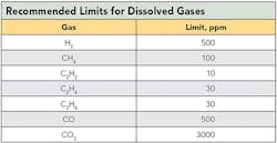
Dissolved gas analysis (DGA) can detect incipient faults developing in CT insulation.
Case Study 1
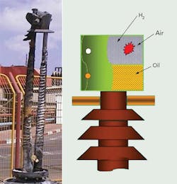
One of the primary windings on each phase of a 170-kV, 1000-A CT, which had been in service for two years, was open circuit for an unknown length of time. The hermetically sealed CT exploded due to the failure of one of its three phases. The explosion caused the ceramic insulator to fragment.
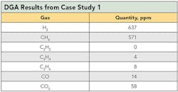
The utility performed DGA on oil samples from the remaining two phases. The results of the DGA confirmed the explosion was a result of generation of the hydrogen in oil.
Case Study 2
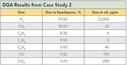
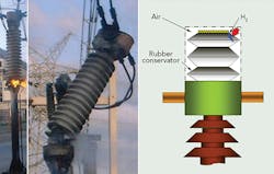
The 170-kV, 1000-A CT had been in service for 20 years. One of the three windings in each phase of the CT was opened before the explosion. The design of this CT had cores in the top part and the oil conservator with resin in a concertina format. The explosion occurred five hours following re-energization and caused damage to the CT with the conservators of two phases being full of gas.
Explosion Mechanism
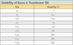
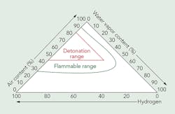
The possible mechanism responsible for the catastrophic results in case studies 1 and 2 is that active partial discharge in oil produces an increasing concentration of hydrogen in the oil volume. The solubility of the hydrogen in transformer oil is the lowest among all the gases. And, solubility of the hydrogen depends on oil temperature. The gas concentration in the headspace of the conservator varies inversely with ambient temperature. Hence, the hydrogen concentration in the bellows will be highest during the coldest period of the day. Climatic conditions may not have a direct influence on the problem, but reducing ambient temperatures may increase the hydrogen concentration in the CT expander.
Water vapor and hydrogen from the oil and air accumulate because of small leaks during the service life. Therefore, the detonation is a self-induced process. During temperature fluctuations, the bellows above the oil expand as a result of hydrogen emerging from the oil. During the expansion process, the possible leakage of the bellow is escalating, allowing the penetration of air. If the gas mixture reaches the detonation or explosion domain, the whole CT will be damaged. Totally sealed bellows will not allow penetrating air, so detonation will not occur even if hydrogen and water vapor exist.
Open Secondary Circuit Protection
To prevent the occurrence of hazardous voltages from abnormal open-circuit conditions in the CT’s secondary winding, IEC has developed an economical and continuous protection device. This device facilitates solid-state nonlinear elements with voltage-dependent conductivity, connected in parallel to the CT’s secondary winding, together with a normally open main thermo switch.
The protection device may further activate, if desired, an alarm circuitry configured to warn an operator about the occurrence of hazardous voltages as a result of an abnormal open circuit in the CT’s secondary winding. An additional thermo-bimetal switch — namely, a signaling contact — is mounted with good thermal contact on the secondary side of the solid-state nonlinear elements. The operating temperature of the additional thermo-bimetal switch is configured to be more than the ambient temperature and less than the operating temperature of the main thermo-bimetal switch.
The protection device comprises dual diode 1 (or two inversely connected diodes) with a cutoff common electrode, connected in parallel to the secondary winding of the CT, together with normally open thermo-bimetal switch 2. The breakdown voltage of the p-n junction of dual diode 1 must be more than the maximum operating voltage normally generated at the secondary output terminal and less than the voltage that would be hazardous.
The operating temperature of the normally open main thermo-bimetal switch 2 (switching on) is configured to be more than the maximum ambient temperature, and the resetting temperature (switching off) is configured to be less than the minimum ambient temperature for a given location. Thermo-bimetal switch 2 is placed with good thermal contact on dual diode 1.
Field Trials
IEC subjected the open-circuit secondary device to field trials on a 170-kV, 1200/5-A CT. When the secondary circuit was open, 3.8 kVrms was sensed at the secondary output terminal. This high voltage was applied to dual diode 1. The diode for maximum blocking voltage (50 V for meter or 200 V for protective relay) broke down instantly and started heating intensively. The resistance of the diode in such conditions was very low (1 Ω to 3 Ω); therefore, voltage across CT terminals dropped instantly from 1380 V to 5 V to 10 V.
Within one second, the diode heated up the signaling thermo-bimetal switch to the pickup temperature and shorted out the signal circuit. Within two to three seconds, the diode heated up the main thermo-bimetal switch to the pickup temperature and shorted out the diode with the secondary winding. The thermo-bimetal switch remained on for a long period of time, until it was either cooled down by the air to -10°C (-14°F) or manually reset, depending on the type of thermo-bimetal switch.
Successful Testing
The continuous protection device was tested successfully in the laboratory and in field trials by opening the secondary windings with current passing through the primary winding. This device is patent pending as IEC seeks cooperation with a manufacturer to produce the device. IEC’s long-term objective is to adopt the device as a utility standard and, when mass produced, it will be available for a global market.
Anatoly Shkolnik ([email protected]) is a senior specialist in the Central Electrical Laboratory at Israel Electric Corp. He has experience in the production, repair, testing and diagnosis of power and instrument transformers. Shkolnik holds a MSEE degree from the Kiev Polytechnic University and a Ph.D. degree in electrical engineering from the Electric Power Research Institute in Moscow, Russia. He is a member of CIGRE SC A2, Transformers and has authored scientific articles and inventions.
Vladimir Gurevich ([email protected]) is a senior specialist in the Central Electrical Laboratory at Israel Electric Corp. He holds a MSEE degree from the Kharkov Institute of Power Engineering and Computer Technology and a Ph.D. degree from National Technical University’s Kharkov Polytechnic Institute. He has authored more than 180 scientific articles, 116 inventions and 10 books.
Mentioned in this article:
Israel Electric Corp. | www.iec.co.il

