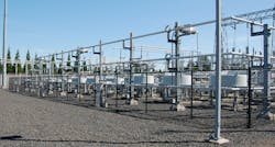
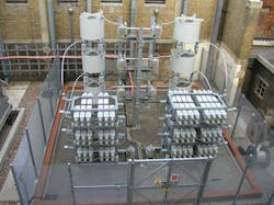
When the electrification process began, generation was located close to the load. As demand increased, generation and loads became farther apart and connected by radial lines. This worked fine for a while, but as demand continued to grow, generation got even farther away, requiring a lot of wire to keep the two connected. It did not take long for utilities to realize that pooling resources helped the situation. Interconnections brought enormous advantages compared to isolated systems such as mingling power, diversification of loads and access to a variety of power sources.
However, there are some downsides to the spreading interconnections. As the networks grow larger, their operation becomes more complicated. The more complex they become, the more susceptible they are to outside forces that affect their ability to deliver power to these far-flung load centers. It also does not help that loads can vary by time of day or that weather conditions affect a transmission line’s rating. As the grid grew, these factors had to be accounted for by mitigation measures. Fortunately, the grid really is just a big electrical circuit that follows all those equations engineers are so fond of.
The physical parameters impacting a network’s power flow and capacity ratings are well understood. They can be compensated for by adding fixed and mechanically switched series and parallel components to the circuit. Typically, reactors and capacitors are added for steady-state control of system voltages, and rotating machines like the synchronous condensers are applied for dynamic compensation. These devices helped tremendously, but, because of the limitations of such conventional equipment in wear and tear (high maintenance) and slow response time, there was a need for more robust apparatus.
The Old with the New
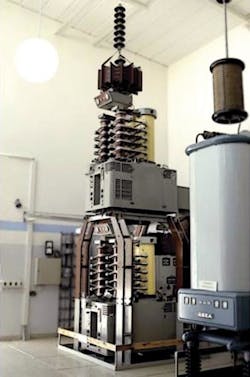
Things started changing by the early 1950s in the unlikely area of high-voltage direct current (HVDC). GE developed the thyristor, which is basically a semiconductor that acts like a controllable unidirectional (diode-like) switch capable of handling high voltages and currents. The thyristor quickly replaced the antiquated mercury arc valve in HVDC converter stations and the world got a lot simpler.
The thyristor proved to be so revolutionary for HVDC technology it should not be surprising that manufacturers began to tinker with it. The solid-state bipolar switching device lent itself to other applications, which opened the door to development of a totally new approach called power electronics. Research and development (R&D) went worldwide with the development of thyristor-based apparatuses for improving system dynamic behavior.
In the early 1970s, this R&D effort resulted in some thyristor-based switching devices that greatly improved their abilities over their mechanical cousins. ASEA (now ABB) introduced a device in 1971 that took a conventional component, the shunt capacitor, and combined it with thyristor technology to form the thyristor-switched capacitor (TSC). The capacitor switching was accomplished by the thyristor within one cycle, which was faster than the traditional mechanically switched devices of the day. They also could be cycled on or off all day, if necessary, rather than the one-and-done philosophy accepted by everyone.
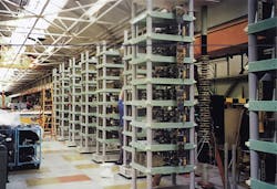
There was no need to limit the TSC’s duty cycle because there were no moving parts. Shortly after the TSC came on the scene, the thyristor-controlled reactor (TCR) device became available. This thyristor application was a conventional shunt reactor controlled by varying the reactor’s current with the firing angle of the thyristor switch (valve). This allowed the TCR to deliver a constantly variable inductive reactance to the connection point.
By applying thyristor technology to these simple shunt devices, manufacturers had the basic power electronic building blocks needed for the new generation of high-tech toys. These solid-state devices could provide smooth, continuous and repeatable control of reactive power necessary for power system control.
FACTS Legos
And building blocks they were. Utility and industrial applications began using TSCs and TCRs, which were quickly dubbed static volt-ampere reactive (VAR) compensators (SVC). The term “static” indicates the device did not have inertia or any moving or rotating parts. These early SVCs were primitive by today’s standards, but it was a start. The first SVCs using TSCs produced no harmonics but could only supply capacitive reactive power in specific steps rather than a smooth, continuous output since the TSC is either fully on or fully off. Combining the TSC with the TCR gave the SVC a continuously variable power output, which was exactly what the grid needed.
By the 1980s, the SVC had become accepted as an alternative technology by both utilities and industrial customers. Today many SVC configurations are available, but the most popular are the TSC, the TCR, a combination of both the TCS and TCR components, and the TSC with a fixed shunt capacitor and TCR component. There also is the variation known as the static VAR system (SVS), which is a combination of a SVC and mechanically switched capacitors/reactors whose outputs are coordinated by the SVC’s controller.
A SVS does not have a uniform volt-current characteristic and its overall response time is dependent on the mechanically switched devices. The big plus is the SVS can operate the utility’s existing substation compensation devices integrated with the dynamic compensation provided by the SVC.
What Is FACTS?
Flexible ac transmission systems (FACTS) controllers proved to be exactly what utilities were looking for in the way of an alternative technology addressing the limitations of the traditional compensation equipment. These solid-state devices had the fast-response characteristics and, most importantly, the cycling ability necessary to tackle the inherent power system restrictions interconnections created. Suddenly, the FACTS acronym was popping up all over the industry as manufacturers brought more power electronics from the laboratories to the grid.
The term came about when Dr. Narain Hingorani, considered to be the father of FACTS, introduced it to the industry in 1985. He talked about the new concept of a thyristor-assisted ac power system at many IEEE and Electrical Power Research Institute (EPRI) gatherings during those early days. The flexible aspect referred to the idea solid-state devices could make the network adaptable to fast-changing system conditions brought about by the power system’s inherent variations. In effect, FACTS gadgets connected to the transmission system would control the flow of power through the system.
To understand the FACTS controllers a little better, the controllers are either variable impedance or voltage-source devices. They are typically classified by their connection topography to the grid:
• Shunt controllers
• Series controllers
• Combined series-shunt controllers
• Combined series-series controllers.
The early TSCs, TCRs and SVCs provided dynamic shunt compensation and proved to the industry that the fast-response power electronics offered had advantages over the standard (that is, mechanical) equipment available. The story of FACTS devices did not stop with this single type of application; it was just the beginning.
New-School Tools
With the advent of the conventional thyristor (that is, no turn-off capability), FACTS technology became hugely popular, but, with the arrival of the turn-off thyristor (such as the gate turn-off thyristor), it was possible to develop a controller, one with more enhanced abilities. Mitsubishi experimented with a FACTS device that included a dc capacitor and whose capacitive and inductive output current could be controlled independent of the ac system voltage.
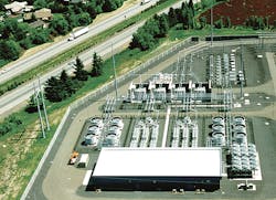
The device was called a static synchronous compensator (STATCOM) and provided dynamic voltage support, stabilization of the power system and improved power quality. The STATCOM has a faster response than a SVC and takes up less space. In 1991, Mitsubishi installed the world’s first utility-sized STATCOM, rated ±80 MVAR, in Japan at the Inumaya substation.
While this was taking place, manufacturers also were working on adapting fixed series capacitors (FSCs) with thyristor technology for switching. To put everyone on the same page, the FSCs are added to a long transmission line to change its electrical characteristics.
FSCs make the line appear to be electrically shorter in distance than it actually is. FSCs substantially increase the loadability of the transmission line, but they also introduced some problems engineers felt the thyristor could alleviate such as stability issues, active power oscillations and subsynchronous resonance (SSR) risks. SSR is one of the more serious issues. It is a low-frequency electromechanical oscillation that can damage or destroy turbine shafts in generators, which actually happened on a utility’s network.
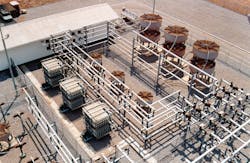
In 1992, Siemens introduced the world’s first thyristor-controlled series capacitor (TCSC) at Western Area Power Administration’s (WAPA’s) 230-kV Kayenta substation. WAPA’s Kayenta 330-MVAR TCSC offered several advantages over the conventional FSC, including flexible continuous control of the desired compensation level applied to the transmission line.
It also provided dynamic overload capability, the ability to reduce fault currents, network power swing damping capability and SSR mitigation, which was perhaps the most important improvement. The TCSC dampened the SSR oscillations on the line, making SSR a nonissue.
Once the TCSC was deployed, engineers and scientists began asking “what if” again, and the static synchronous series compensator (SSSC) emerged.
The TSCS is a variable capacitive impedance that injects voltage proportional to the current. The SSSC injects variable voltage of either polarity in quadrature with the current much like the STATCOM; therefore, why not combine the SSSC with the STATCOM? That is exactly what EPRI, Westinghouse and American Electric Power (AEP) did, developing the world’s first unified power flow controller (UPFC) in 1998 at AEP’s Inez substation.
Typically, a UPFC has two voltage source inverters that share a common dc storage capacitor connected to the system through coupling transformers. One inverter is connected in series using a series transformer, and the second inverter is connected by a shunt transformer. This gives the UPFC many possible operating modes such as VAR control mode, automatic power flow control, phase-angle shifter and automatic voltage control among others.
With each of these FACTS controllers, the collection of controllers grew, and FACTS technology provided more solutions to the limitations the power system had been dealing with since the rise of the interconnections.
Thyristors or Transistors
By the mid-1990s, there was a brand-new design for HVDC technology. ABB brought out the voltage source converter (VSC) based on the insulated-gate bipolar transistor (IGBT) for the valve design. The first VSC HVDC application to be deployed was the Hallsjon pilot project in Sweden in 1997. It was very successful and it did not take long before the IGBT technology was being adapted to FACTS technology.
The VSC-based controller is a self-commutating power semiconductor device that tends to be smaller and more compact. It also can supply reactive power at relatively low values of the bus voltage and can be designed to have a built-in short-term overload capability.
The first application of the IGBT VSC technology for FACTS controllers was ABB’s 0-MVAR to 44-MVAR SVC installed in 1999 at the Uddeholm Tooling steel plant in Hagfors, Sweden. The VSC-based IGBT FACTS controller is connected to a capacitor, which acts as a dc voltage source. Hagfors took advantage of pulse-width modulation (PWM) technology, too. PWM allows switching to take place in the kilohertz range, which provides a very smoothing voltage output from the device, removing the flicker caused by the electric arc furnace.
It Is Dynamic
It has been more than three decades since Hingorani announced to the world a new concept in power system control — called FACTS — and today this concept is considered a proven and mature technology. R&D work has continued to produce a wide assortment of high-power FACTS controllers that address just about every issue facing transmission operators. More importantly, they can be installed individually or in combination with other FACTS widgets to control one or more interrelated parameters or variables of the transmission system.
As utilities push the grid to get more watts through it, they are getting closer to its limitations and need all the advanced technological help that can be mustered. That is exactly what is taking place with the new types of FACTS devices coming out of the laboratories today.
These wonders of power electronics bring several benefits to the grid, including an improvement in the dynamic behavior of the system, increased load capabilities of the network and enhancement of the grid’s reliability. The exact type of controller is determined by the nature of the problem being addressed. Fortunately, operators today have many options because of the continuous advancements in FACTS technology.
About the Author
Gene Wolf
Technical Editor
Gene Wolf has been designing and building substations and other high technology facilities for over 32 years. He received his BSEE from Wichita State University. He received his MSEE from New Mexico State University. He is a registered professional engineer in the states of California and New Mexico. He started his career as a substation engineer for Kansas Gas and Electric, retired as the Principal Engineer of Stations for Public Service Company of New Mexico recently, and founded Lone Wolf Engineering, LLC an engineering consulting company.
Gene is widely recognized as a technical leader in the electric power industry. Gene is a fellow of the IEEE. He is the former Chairman of the IEEE PES T&D Committee. He has held the position of the Chairman of the HVDC & FACTS Subcommittee and membership in many T&D working groups. Gene is also active in renewable energy. He sponsored the formation of the “Integration of Renewable Energy into the Transmission & Distribution Grids” subcommittee and the “Intelligent Grid Transmission and Distribution” subcommittee within the Transmission and Distribution committee.

