The development of power electronics technology and applications in industrial automation have resulted in the installation of AC-DC-AC inverters, now commonly used because they offer excellent speed control and energy savings. Short-time voltage drops (that is, voltage sags and dips) often occur on transmission systems and distribution networks for various reasons. Although they have little impact on traditional electrical devices, these voltage disturbances can cause an inverter to trip due to the lack of low-voltage protection, a phenomenon particularly serious to production processes if motors driven by inverters cease to operate. Every unplanned outage caused by voltage sags can result in economic losses and, in severe cases, could threaten personal safety or the environment.
In January 2011, a single-phase current transformer failure in a 500-kV substation on the Northeast China Power Grid resulted in grounding the 500-kV bus bar. The installed fault recorder indicated the phase voltage of the 500-kV system dropped from 535 kV to 16.8 kV, and the voltage on a 6-kV network in a thermal power plant dropped by 65%, causing the low-voltage protection on all the coal feeder inverters to trip. The boiler furnace fire protection went into operation, averting a serious incident and thereby restoring the safe, stable operation of the 500-kV transmission system.
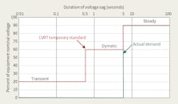
The basic reason the thermal power unit tripped was a result of voltage sag that caused the low-voltage trip of the coal feeder inverter and main fuel trip to operate. In thermal power plants, voltage sags are referred to as low-voltage ride through (LVRT). This incident resulted in the Northeast China Power Grid arranging for all power plants to improve the LVRT ability of thermal unit auxiliaries. Then in 2012, the China State Grid Corp. issued a temporary standard for thermal power unit auxiliaries. The effort to improve the LVRT ability of thermal power unit auxiliaries was launched nationwide.
Voltage Sag Standards
The impact of voltage sags can have similar serious implications for other industries with continuous processes, such as the coal, oil, chemical and semiconductor industries, where inverter-driven motor drives are installed. In European countries, voltage sags and short-time interruptions have been a long-term problem, and statistics indicate these operating characteristics of transmission systems account for 80% of customer complaints.
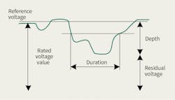
According to the Institute of Electrical and Electronics Engineers (IEEE), voltage sag is defined as a root-mean-square (rms) variation with a magnitude between 10% and 90% between 0.5 cycle and one minute. The International Electrotechnical Commission’s (IEC’s) definition for voltage sag differs from the IEEE standard in the magnitude of voltage sag. According to IEC, voltage sag is a rms variation with a magnitude between 1% and 90% between 0.5 cycle and one minute.
When the voltage’s effective value reduces to close to zero and continues for some time, this is known as a short interruption. There is no strict distinction between voltage sags and short interruptions, and the protection solutions are similar. There are many causes for voltage sags, but they are mainly the result of all types of short circuits, overloading, grounding and the starting of a large motor.
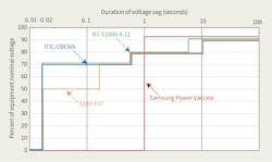
In this digital era, the impact of voltage sags on industry is increasing. Therefore, the IEC, Computer and Business Equipment Manufacturers Association (CBEMA), Semiconductor Equipment Materials International (SEMI) and Samsung conducted research into the voltage tolerance of electrical equipment and identified four main standards of voltage sags.
Inverter Impact
An inverter comprises two parts, the AC-DC rectifier and the DC-AC inverter. In the design of the AC-DC-AC inverter, the DC bus is the intermediate link. The low-voltage protection values of the DC bus are different according to the types of inverter and generally 85% of the rated value. Some can reach 62% of the rated value, but in actual operation, this will cause overcurrent protection.
The inverter generally has low-voltage, overvoltage and overcurrent protection. Once a voltage sag or short interruption occurs, the DC voltage will drop. The protection acts when the DC bus voltage drops down to its low-voltage protection value, leading the inverter to trip.
When the installed device is an insulated-gate bipolar transistor, the inverter operates for a short time (td) during the voltage sag or short interruption. In the voltage sag or short interruption duration (
Voltage Sag Protection
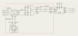
In general, the design of the inverter’s AC-DC-AC structure enables the voltage sag problem to be overcome from the DC link, by providing DC voltage for the inverter’s DC bus. This practice is called DC support technology, namely, providing voltage support for the inverter’s DC bus during voltage sags to ensure normal operation of the inverter’s DC-AC components and provide a stable AC output voltage so the motor will not stop working.
Voltage sag protection (VSP) systems based on DC support technology can be divided into two types, one that uses residual voltage and one that uses a small number of batteries as the energy source. The output of both VSP systems is connected to the load side of the inverter’s DC bus.
When the AC voltage is normal and the VSP system is in standby mode, the inverter is supplied by the transmission system or distribution network. In the event of voltage sag, the VSP system operates automatically by detecting the change in AC voltage and commences to time the event.
There are two types of VSP systems — a stable DC output voltage of 500 V (protected inverter of AC 380 V) or DC output voltage of 1000 V (protected inverter of AC 690 V) — to support the inverter DC bus for ensuring continual operation. When the power grid recovers, the VSP system automatically ceases operation and discontinues the timing.
The VSP system using residual voltage is mainly composed of a VSP module, control cabinet and feeder cabinet. VSP systems using batteries are mainly composed of batteries, a charger, a VSP module, a control cabinet and a feeder cabinet.
The VSP module adopts boost technology comprising an input capacitor, an inductor, a switch tube, diodes and an output capacitor. With the VSP module, the input voltage can be set up to five times the maximum value. The VSP module using residual voltage only needs to add a bridge rectifier to enable the boost circuit to step up the residual voltage. The battery-based VSP system requires battery capacity selected in accordance with the power of the protected device and support time.
Case Study 1
A thermal power plant experienced a boiler shutdown event due to a coal feeder inverter trip during voltage sag, which posed a serious threat to safe operation of the transmission system. Therefore, it was necessary to improve the ability of the coal feeder inverter to withstand voltage sags. The requirement was to guarantee normal operation of the inverter when AC voltage dropped to 20% to 90% of the rated value.
To satisfy the requirements of the power plant, there was no need to consider the voltage sag, which dropped to below 20% of the rated value and short interruptions. Therefore, the VSP system using residual voltage was deemed suitable for being equipped on each coal inverter.
A single-phase ground fault occurred on a 500-kV transformer, leading to the auxiliary power supply voltage dropping to 20%. The application remained effective when the AC input voltage dropped to 20%. With the support of the VSP system, the inverter DC bus voltage was maintained and the stable AC output voltage ensured the coal feeder remained in continuous operation during the voltage sag.
Case Study 2
A methanol and ammonia cogeneration chemical plant producing some 600,000 tons per year was subject to an unplanned outage resulting in serious economic losses. The liquid oxygen pump inverters and liquid nitrogen pump inverters in the air separation unit tripped during voltage sags, which ultimately tripped the interlock system on the complete production line. Hence, the inverters required protection from voltage sags.
The liquid oxygen pump inverter had the following specifications:
• ABB ACS800 inverter with AC voltage of 690 V
• Frequency in use of 50 Hz with full power
• Three 315-kW motors, with two running and one idle
• Installed power of 945 kW with actual power of 630 kW
• Support time of three minutes.
The VSP system with batteries was used to protect the liquid oxygen pump inverter from both voltage sags and short interruptions. Each inverter has an output circuit comprising three loops and three sets of batteries in parallel to provide voltage support.
A transmission line fault caused the outage of the high-voltage/medium-voltage transformer to trip, resulting in a large-scale interruption in the factory. The short interruption lasted for 10 seconds. Operation of the VSP system confirmed the input AC voltage dropped, but with the support of the VSP system, the inverter DC bus voltage (1000 V) provided a stable AC output voltage that ensured the liquid oxygen pumps would operate continuously during short interruptions.
VSP Systems
In both case studies, the voltage sags and short interruptions were created by operational incidents on the extra-high-voltage system. However, voltage sags and short interruptions can be created by incidents on the medium- and low-voltage distribution networks, resulting in the same outcome, namely the AC voltage drops of the inverters. The VSP systems could suppress voltage sags and short interruptions that occur on both the transmission systems and distribution networks. The VSP system was designed and developed by the Nanjing Golden Cooperate Co. Ltd., which supplied and installed the equipment in the cabinets.
The market for VSP systems has grown in the last 10 years, as the systems have been installed throughout China for more than 500 customers in numerous industries. In total, 2000 VSP systems have been installed with a total installation capacity of 100 MW. The installation of the VSP systems has resulted in an annual customer savings of US$460 million. All large customers with continuous production processes would benefit from installing VSP systems and could recoup the costs from savings arising from a reduction in production downtime.
Successful Solutions
Voltage sags are an inevitable phenomenon in the operation of transmission systems that can cause sensitive loads such as inverters installed in end-user plants to stop working, resulting in large economic losses in continuous production plants. Combined with the AC-DC-AC characteristics of inverter and power electronic technology, two types of voltage sag protection systems based on DC support technology have been designed, developed and installed in China.
Field applications have confirmed both types of VSP systems have been rigorously tested by transmission system outages and successfully demonstrated they satisfy the VSP design specification by ensuring uninterrupted operation of motor-driven inverters during voltage sags and short interruptions.
Acknowledgement
The author wishes to thank Chen Zhigang of Chongging Wansheng Coal-Chemical Co. Ltd. and Li Wang of Golden Cooperate Co. Ltd. for their support of this article.
Zhu Xuezhong is an associate professor in the College of Automation Engineering at Nanjing University of Aeronautics and Astronautics. A member of the national aviation power supply experts, Xuezhong’s main interest is in research on power electronics and power drives. In addition, he is a leader in R&D linked to military projects, equipment and all types of DC conversion modules.
About the Author
Zhu Xuezhong
Zhu Xuezhong is an associate professor in the College of Automation Engineering at Nanjing University of Aeronautics and Astronautics. A member of the national aviation power supply experts, Xuezhong’s main interest is in research on power electronics and power drives. In addition, he is a leader in R&D linked to military projects, equipment and all types of DC conversion modules.


