Xcel Energy's New Aesthetic GIS Substation Provides Reliability
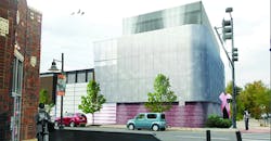
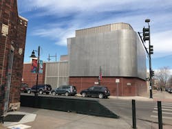
It was time for change in downtown Denver, Colorado, U.S., when a legacy air-insulated substation with a straight bus and aging metal-clad switchgear could no longer meet the capacity demands and North American Electric Reliability Corporation reliability requirements. For the solution, Xcel Energy partnered with Burns & McDonnell to design a gas-insulated substation (GIS) that would meet system protection and reliability requirements in a compact space as well as provide considerable visual appeal to the everyday passerby.
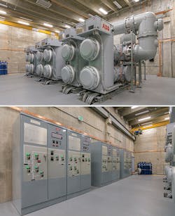
The 115-kV GIS switchgear uses sulfur hexafluoride (SF6) insulating gas and is appropriately rated for continuous and fault interruption current requirements. By using 3-D modeling, closely coordinating all parties, and implementing novel design and installation ideas, the GIS enclosure was built within the strict confines of the property size, existing equipment and required balance-of-plant equipment for the 115-kV GIS.
Pieces to the Puzzle
Eight years ago, Xcel Energy envisioned the ultimate five-phase plan. Execution of the plan kicked off in 2012 with an in-depth zoning analysis to determine both the historical status of an abandoned 1940s-era 4-kV substation building and the viability of reusing the building for the new GIS. The goal of the zoning application was to build a state-of-the-art substation that would blend with the existing architecture and surroundings, preserve the pedestrian-friendly main street and provide an attractive gateway to a growing arts district.
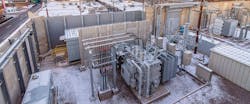
Xcel Energy determined the old 4-kV substation building did not have historical status, and because it could not be repurposed for the new GIS equipment, the building was removed. This provided vital space for adding a third 40-MVA transformer on the 115-kV bus and associated medium-voltage metal-clad switchgear.
This phase 1 addition effectively set the stage for the outages needed to put into service all subsequent phases of work without impacting system reliability requirements. Phases 2 and 3 followed with the construction of the GIS enclosure as well as the 115-kV, six-position GIS ring-bus interconnected to one of the three underground 115-kV transmission circuits and one of the three transformer positions.
Future phases 4 and 5 will interconnect two remaining underground 115-kV circuits and transformers #1 and #2 to the GIS. Additional planned projects will add new distribution switchgear lineups in the space formerly occupied by the 115-kV air-insulated substation breakers, switches and bus work. The old electrical equipment enclosure (EEE) will be removed after the staged transfer of existing relay, control and communications circuits to the GIS enclosure.
Extreme Challenges
When it came down to the design and construction of the new GIS in the urban space, Xcel Energy had to overcome many extreme challenges:
• Property limitations. Busy arterial streets and pedestrian sidewalks adjacent to the property line required costly permits to close or obstruct the streets. Holidays and special events prohibited street closures, which added to the scheduling and construction challenges. Furthermore, on-site construction parking and laydown areas were not available. Because of the location, frequent tagging of Xcel Energy facilities require anti-graffiti coatings on all street-side surfaces. Another challenge of the property — particularly due to the limited access to equipment and a laydown area — was the low-bearing capacity of the sandy soil, as piers or piles were required to provide support for the foundation.
• Existing equipment. Work was performed near energized high-voltage bus and equipment, and the existing protective relaying could not withstand large vibrations during construction. In addition, the existing EEE obstructed access to the control and power circuits from existing substation equipment into the new GIS enclosure.
• Underground interferences. Existing underground high-voltage and medium-voltage circuits were located near proposed construction. As-built documentation of these circuits was not accurate, compared to the encountered field conditions. In addition, the existing precast perimeter wall and associated foundations obstructed the GIS enclosure footprint.
• Cable heating and ampacity. Several circuit crossings with medium-voltage feeder circuits required an ampacity study of the underground high-voltage circuits to determine the heating and resulting current-carrying capacity of the affected cables.
3-D Modeling Is Key
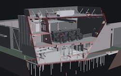
With multiple engineering disciplines jostling for every available cubic-foot to minimize the work footprint, 3-D modeling was used to enable collaboration early in the design process so conflicts and interferences could be avoided. The 3-D modeling program identified space issues and enabled all engineering disciplines to quickly assess design changes to the enclosure.
The 3-D model was used to perform many tasks, including structural analysis; locating electrical and heating, ventilation and air conditioning equipment as well as ductwork; routing the cable tray; and providing working, installation and maintenance clearances. The manufacturer of the GIS provided a 3-D model of its product with the necessary working space clearances to model the equipment accurately in the GIS hall.
The 3-D model also enabled the Xcel Energy operations and maintenance group to take a virtual tour of the enclosure. This helped the group to visualize the space and provide comments that included the most important guideline of making it safe and keeping it simple, so typical maintenance and alarm issues could be addressed safely without requiring third-party assistance.
Two critical space and access issues were identified with the help of the model. First, a portion of the existing perimeter wall obstructed the GIS enclosure. Fortunately, an expansion joint in the precast panels provided an opportunity to remove the section without saw-cutting, which could compromise the structural integrity of the wall. Second, because the phase orientation of the underground transmission circuits entering the GIS enclosure were not consistent, the 3-D model was used to show an efficient way for the future installer to route the high-voltage cables and transition the phases for the correct interface with the GIS termination modules. Additionally, modeling these cables helped to confirm the locations of preinstalled, street-level conduit chases in the precast walls for future 115-kV cable installation.
The elbowing for space even extended below grade with the existing EEE obstructing control cable raceway access into the garden level of the GIS enclosure. The problem was solved by installing four 20-inch (508-mm) pipe casings beneath the EEE foundation using the jack-and-bore method to avoid vibrations that could cause inadvertent relay operation and accommodate the installation of control cable conduits to existing substation equipment.
Underground Ampacity Study
Several crossings of the new 115-kV underground circuits and existing medium-voltage feeders were identified during the detailed design of the ultimate general arrangement. A tabletop audit of the medium-voltage circuit loadings was performed, and information on the new and existing cables was assembled to perform an ampacity study that modeled the overall heating effects, especially at each cable crossing.
The study determined the maximum allowable loadings to avoid cable degradation or failure, and the 115-kV circuit paths and burial depths were modified to meet the desired normal and emergency ratings for all circuits.
Congestion Alleviated
To reduce excavation costs and minimize the impact of possible flooding, the underground high-voltage cable spreading room is located at the garden level, with the main floor of the GIS hall directly above it. The relay and control room is located at the mezzanine level, above the battery room and overlooking the GIS hall. Multiple iterations of the layout were used to reduce the overall size of the enclosure, minimizing costs and accommodating site constraints with existing facilities.
The method of supporting the enclosure foundation was addressed in the geotechnical report, which gave three options for consideration. Drilled concrete piers were not used because of concerns with sandy soil cave-in and limited site space for drilling rigs and pier casings. While economically attractive, driven piles posed a vibration risk to the existing protective relaying located in the adjacent EEE. Finally, helical piers were selected, and the higher installation cost was nearly offset by the speedy installation of more than 60 piers with small-footprint equipment and the low risk to inadvertent relay operations.
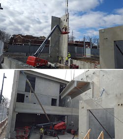
Electing to build the GIS enclosure with precast, or prestressed, wall and floor panels rather than cast-in-place or concrete masonry units was an important way to keep it simple, given the significant site access and laydown area constraints, schedule requirements, and busy urban streets and sidewalks.
The precast wall and floor panels were manufactured at a nearby facility with an insulated core for energy efficiency, and the double-tee floor decks were designed to meet very tight flatness tolerances required by the GIS manufacturer. Brick veneer was used to complement the existing perimeter wall. Delivery of the precast wall panels and floor decking was scheduled to enable crane picks directly from the delivery tractor-trailer. The panels and decking were erected in less than a week with minimal street and sidewalk closures. The precast method also enabled the installation of the GIS bridge crane prior to the installation of the roof deck panels.
Enclosure Systems and Life Safety
The keep-it-simple concept extended to the design of the GIS enclosure systems and life safety requirements. Off-the-shelf touchscreen controllers were selected in lieu of a complex building automation system for each air-handling and makeup air units. The only conditioned air spaces are the relay room and battery room. Station alarms for high and low enclosure temperatures are standard-issue design.
Given the GIS enclosure size, material composition and occupancy classification, no fire suppression system was required. Emergency egress paths were carefully designed to meet all life safety codes. An aspirating-type smoke-detection system integrated with a main fire-alarm panel provides very early-warning fire detection to Xcel Energy system operations dispatch. Additionally, an oxygen-depletion alarm system was provided, given operations crew concerns that SF6, while nontoxic, is a heavier-than-air gas. Battery room ventilation and hydrogen-gas detection alarms are included and integrated into the addressable data bus of the fire-alarm system.
Turnkey Coordination
It is easy to forget the beating heart of the new facility is the high-voltage GIS switchgear, considering the extensive and complex balance-of-plant systems needed to support the functioning of the gear. During the design, close coordination between the GIS manufacturer, Xcel Energy and Burns & McDonnell occurred during several in-person and conference call meetings.
After the design, the next challenge to coordinate became the delivery and installation of GIS equipment at the space-constrained site. Because no other construction activities were permitted while turnkey personnel were on-site, a GIS manufacturer representative inspected the condition of the facility for completeness and cleanliness before mobilizing the crew. The physical assembly, wiring to local control cabinets, and testing and commissioning of the GIS was performed by the switchgear manufacturer.
Mission Accomplished
By using 3-D modeling, closely coordinating all parties, and implementing novel design and installation ideas, the GIS enclosure was built within the strict confines of the property size, existing equipment and required balance-of-plant equipment for the 115-kV GIS. With the GIS and enclosure now installed and commissioned, Xcel Energy can move forward with the final phases of transitioning the 115-kV elements into the GIS. This substation will greatly benefit system reliability on the 115-kV transmission system, and the compact nature of the GIS enables future installation of new switchgear lineups to enhance further reliability of the medium-voltage distribution network in downtown Denver. ♦
Brian Richter is a registered professional engineer in the state of Colorado and senior manager of substation and transmission engineering outsourcing at Xcel Energy. His background is in substation engineering and design as well as protective relaying.
Charlaine Douden is a member of the substation and transmission engineering outsourcing team at Xcel Energy, with more than 30 years of experience in design and project management of substation projects.
Janson Ferrera is a registered professional engineer and project manager at Burns & McDonnell, designing substation projects for major utilities. His project experience spans a wide range of scopes for greenfield and brownfield sites, including engineering-only and engineer-procure-construct project delivery methods.
Editor's note: Xcel Energy and Burns & McDonnell will host a tour of the substation on April 18 during the 2018 IEEE PES T&D Conference & Expo. Registration is limited. This project also will be presented during the IEEE Young Professionals Project panel session at the conference.
Check out the March 2018 issue for more articles, news and commentary.
About the Author
Brian Richter
Brian Richter is a registered professional engineer in the state of Colorado and senior manager of substation and transmission engineering outsourcing at Xcel Energy. His background is in substation engineering and design as well as protective relaying.
Charlaine Douden
Charlaine Douden is a member of the substation and transmission engineering outsourcing team at Xcel Energy, with more than 30 years of experience in design and project management of substation projects.
Janson Ferrera
Janson Ferrera is a registered professional engineer and project manager at Burns & McDonnell, designing substation projects for major utilities. His project experience spans a wide range of scopes for greenfield and brownfield sites, including engineering-only and engineer-procure-construct project delivery methods.
