Maintaining transmission lines and structures in a 30,000-sq-mile (78,000-sq-km) service territory has a distinctive set of trials on any given day. Oklahoma Gas & Electric (OG&E) owns and operates transmission lines at voltages from 69 kV to 500 kV across its system, which consists of approximately 5700 miles (9173 km) of single H-Frame lattice tower structures and a few specialized structures. These lines cross the service territory in sometimes challenging conditions and circumstances. The National Electrical Safety Code is used as a minimum design standard and to combat the effects of common weather occurrences such as high winds, severe thunderstorms, tornadoes and ice storms.
Even with more than a century of experience in dealing with the negative impact of Mother Nature, OG&E recently faced a situation unlike any other weather-related complications of the past. May 2015 was the wettest month in the history of Oklahoma, U.S. An astounding 14.40 inches (366 mm) of rain saturated the OG&E service territory. The previous record rainfall was 10.75 inches (273 mm) in October 1941. This amount of rainfall has a direct impact on the way creeks, rivers and streams change course. All major streams in Oklahoma have broad sand-filled channels with active water courses occupying a small portion of the riverbed or floodplain. An abundance of water discharge or flooding can cause these channels to shift dramatically.
A transmission lattice tower crossing in what had been a stable location for a number of years washed into one of these rivers on June 15, 2015. Because it was a tie line between two power plants, the transmission line was critical to continuing operations. A contingency analysis by the control center indicated an urgency to restore the line to service. Initially, the design team planned to replace the lattice structure with a single-pole structure of the same configuration, phase spacing and strength. In normal conditions, this direct replacement would have worked. However, in this instance, the structure would have to be relocated because of the changing river course. In addition, the initial replacement solution was feasible for normal soil conditions but not near rivers and streams. The utility had to consider the alternatives.
Alternative Solutions
The next alternative was to examine another route for the line to make the connection on the opposite side of the river. Fortunately, the reroute was relatively short and involved one landowner. Another fortunate circumstance was that the new tie would not involve another river crossing. The reroute could use the existing design standards and structure configurations that had been used previously. The initial site survey indicated soil conditions were favorable for the reroute. Unfortunately, negotiations with the landowner were not as fruitful as was hoped.
While this first alternative was being worked through, designers concurrently developed structures for each side of the river crossing. Reasonable locations in the existing alignment were chosen for the washed-out structure and the adjacent structure. The resulting span length was 1575 ft (480 m), in which two structures would replace three of the existing tower structures.
Soil tests were taken for the two new locations. The tests revealed these structures would need to be designed as two-pole vertical self-supporting dead-end structures to support the two circuits tying the power plants together. Design parameters are full dead-end loading on one side of the structure and full circuit loading with broken conductor on the other side of the structure. As a result, concrete foundations were projected to be 10 ft (3 m) in diameter and 35 ft (11 m) deep. Foundation costs for this proposal alone totaled nearly as much as the structure itself.
Alternative Structure
OG&E then enlisted alliance partner Valmont Utility to propose costs for this structure along with a timeline for manufacturing and delivery. In its response, Valmont Utility presented another alternative, one that would use its PyraMAX structure. This structure is scalable and offered in a family of designs that address projects consisting of lattice, large spans, transposition, dead-end and crossing structures.
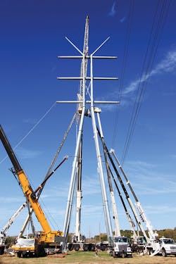
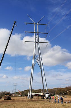
The PyraMAX structure is designed like a lattice tower structure. The structure carries vertical, longitudinal and transverse loads that create moments in the structure. The battered legs and bracing are positioned to carry these loads, primarily as axial loads down to the foundation. Basically, the force of the moment is carried within the foundation as opposed to reactions carried within the original two-pole, vertical self-supporting dead-end structure foundation design.
Because the force travels with the axis of the leg, the structure requires the use of four structural members instead of two, which results in a reduction in foundation size and depth. Savings in concrete and steel cage costs are realized immediately. The PyraMAX structure also requires less labor compared to a lattice structure, because fewer structural members need to be connected. Design, modeling and full-scale testing of the lattice alternative also is avoided. The sections are lightweight and can use multiple foundation sizes, so the structure can be installed where terrain — that is, the soil condition — presents challenges.
Because these designs are offered as a family, there is a significant reduction in time from design to installation. The original concept for this application would have taken design, review and approval time by engineering personnel of both the utility and Valmont Utility. These applications range from 100 ft to 500 ft (30 m to 152 m) in a single circuit up to six circuits. The voltage range is from 66 kV to 1000 kV. Once an application from the family is selected for a long span or lattice tower replacement, fabrication can begin.
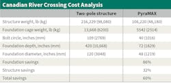
The table describes application differences with the conventional two-pole structure versus the PyraMAX structure. The structure weight was one of the main constraints because the structure would be in sandy soil. Another important consideration was the foundation diameter and depth. Clearly, there is a savings in structure and foundation costs.
Structure Construction
The contractor was enlisted to form and pour the concrete foundations as specified. The recommendation from both internal and external engineers was to let these foundations cure for no less than 30 days and to test the foundations at certain intervals to ensure structural integrity.
Because of the May rainfall, internal transmission construction resources were involved in emergency and restoration activities, or were involved with work that had been scheduled several months in advance. Thus, OG&E used a transmission contractor with the technical assistance of Valmont Utility to assemble the two structures.
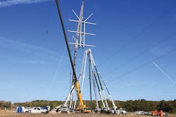
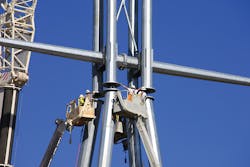
The contract crew assembled the four legs and the top of the structure in one day on the ground. They then erected each structure the following day. They used five cranes to assemble the structure in a short amount of time. Four of these cranes were used to assemble and hold in place the legs of the structure, while the fifth was used to lift and set the body in place.
Success for the Future
The PyraMAX structures provided OG&E with a solution to a challenge it could face again. It is certain that rivers and streams will continue to change course. Also, the application is well suited for limited-access highway crossings. The footprint of the structure fits within right-of-way provisions and landowners have responded favorably to its appearance.
May 2015 was an epic month for severe weather in Oklahoma. The unprecedented amount of rainfall was accompanied by tornadoes, high winds, hail and flooding, which led to challenges across OG&E’s generation assets, extensively damaged delivery facilities and caused more than 170,000 customer outages. Resources were strained, to say the least. It was time to think outside the box for solutions and engage internal resources, vendors and contract services. At OG&E, that is called achieving together. ♦
Leroy Kirk III is the manager of transmission and substation engineering for Oklahoma Gas & Electric. He holds a BSEE degree from the University of Oklahoma and a MBA degree from Oklahoma City University. He is a registered professional engineer in the state of Oklahoma.
Sidebar: About OG&E
Oklahoma Gas & Electric Co., a subsidiary of OGE Energy Corp., is Oklahoma’s largest electric utility. For more than a century, the utility has provided customers in Oklahoma and western Arkansas with the safe, reliable electricity needed to power businesses and homes at rates below the U.S. national average. OG&E employees are committed to generating and delivering electricity, protecting the environment and providing excellent service to more than 836,000 customers.
OG&E has 6700 MW of electric generation capacity fueled by low-sulfur coal, natural gas, wind and solar. OG&E is recognized as a leader in smart grid technology, leveraging this platform to provide its customers with the award-winning SmartHours program and setting the stage for an electric vehicle program that will include some level of public charging infrastructure as well as advanced light-emitting-diode lighting. OG&E employees live, work and volunteer in the communities they serve.
About the Author
Leroy Kirk III
Leroy Kirk III is the manager of transmission and substation engineering for Oklahoma Gas & Electric. He holds a BSEE degree from the University of Oklahoma and a MBA degree from Oklahoma City University. He is a registered professional engineer in the state of Oklahoma.
