Utility Relocates Two Complex Underground Transmission Circuits
A major public works stormwater project in Denver, Colorado, U.S., required Xcel Energy to relocate two 115-kV high-pressure fluid-filled underground transmission lines. To be successful, the utility had to do the following:
- Work within two short outage windows
- Meet an inflexible completion deadline that provided less than half the usual time to complete similar projects
- Perform complex engineering designs in four months
- Find solutions to overcome long lead-time windows for replacement high-pressure fluid-filled (HPFF) cable
- Design a route through business and residential streets that were both crowded and historic
- Coordinate design and material for three separate construction sites
- Design and build termination structures in tight substation spaces
- Adapt design during construction to accommodate undocumented underground utilities.
Xcel Energy called on POWER Engineers to design the two lines in phases and move each design to construction as crews completed each phase. Through open communication and careful scheduling, coordination and construction meetings with both the city and county of Denver, Xcel Energy crews, POWER and contractors kept the project moving ahead in a timely manner.
Historic Project
In June 2016, Denver notified Xcel Energy that a proposed storm channel would affect approximately 4450 ft (1.4 km) of about 12,640 ft (3.9 km) on two underground transmission circuits. Several months later, the utility learned the channel work would start in November 2017. The city had a strict deadline to complete the largest stormwater channel project in its history by Sept. 1, 2019.
The project would relieve frequent flooding in the city’s historic north and northeast neighborhoods. The stormwater problem area was in the Montclair basin, the largest basin in Denver, comprising 9.5 sq miles (24.6 sq km). It did not have enough drainage for stormwater to flow to the South Platte River. Drainage work on a second basin, Park Hill, gave the project its Two Basins name.
To provide the needed outflow path, Denver Public Works designed Platte to Park Hill (P2P) as four connected projects to create a major drainage system. Integral to the system was the 39th Avenue greenway, a broad, open channel with detention ponds and park-like green space. The greenway would convey floodwater safely to an outfall at Globeville Landing Park on the Platte River.
Transmission Impact
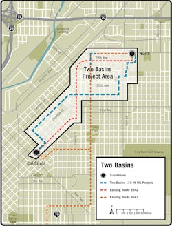
The stormwater channel path flows east to west along 39th Avenue, passing Xcel Energy’s North substation near York Street on its way to the Platte River. The western portion of the path passes over Xcel Energy’s transmission line 9542, a 115-kV HPFF underground line. Once the line exits the substation, it runs beneath 39th Avenue.
Just east of Franklin Street, the drainage channel enters a 500-yard-long (457-m-long), 12-ft x 15-ft (3.7-m x 4.6-m) concrete box culvert that empties stormwater into the Platte River at Globeville Landing Park. In this area, line 9542 turns south on Walnut Street until it connects to Xcel Energy’s California substation. Dubbed the North California line, 9542 was the longer of the two relocation projects at 2.7 miles (4.3 km).
Also in the channel culvert area is Xcel Energy’s transmission line 9547, a second 115-kV HPFF underground line originating at North substation. It travels south on Franklin Street from 40th Avenue and crosses line 9542 at 39th Avenue to the Capitol Hill substation. The same concrete box culvert that affects the North California line also runs directly into this North Capitol Hill line at the intersection of Franklin Street and 39th Avenue.
To make room for the installation of the box culvert, a 1200-ft (0.57-km) section of the North Capitol Hill line had to be relocated deeper to pass beneath the planned new drainage box culvert.
The existing 9542 line consisted of a kraft paper-insulated, 1250-kcmil copper-conductor cable system. The existing 9547 line was a laminate paper-insulated, 2250-kcmil copper-conductor cable system between the two substations. In addition to connecting the North and Capitol Hill substations, line 9547 also provided an emergency feed to the California substation by way of a kraft paper-insulated, 1250-kcmil copper-conductor cable system originating at a wye splice located near the midpoint of the line. The wye splice would be used to feed the California substation during the cutover to the new 9542 circuit.
To further complicate the project, Xcel Energy had just two six-week outage windows to do the cutover work. One began in October 2017, when the weather was cooler and the power demand lower.
In that time, the utility had to remove the old HPFF transmission line and termination structures plus install new cross-linked polyethylene (XLPE) cable and termination structures.
The next outage window was in April 2018, when demand for heating dropped. At that time, the shorter North Capitol Hill 9547 line was relocated.
Cable System Quandaries
Relocating the transmission lines presented Xcel Energy with several puzzles. Relocation of the shorter North Capitol Hill 9547 line seemed to be the easier issue to resolve. A 640-ft-long (140-m-long) horizontal directional drill could help to relocate the transmission line below the drainage channel, with all the work done in the existing street right-of-way.
Relocating the North California 9542 transmission line presented more complex issues. One question was whether to relocate only the portion of the line affected by the storm channel installation and keep part of the HPFF cable system in place, or relocate the entire line using a XLPE cable system.
The existing HPFF line had a limiting ampacity and Xcel Energy’s operations and planning staff desired greater ampacity than the existing 688 A.
Additionally, the integrity of the pipe was unknown. The utility would need to run an inspection gauge, called a smart pig, down the existing pipe before doing any re-cabling. The existing pipe also would enable re-cabling only with a 2250-kcmil cable.
A limited number of HPFF cable suppliers and the uncertainty of getting replacement cable on time also raised major concerns. Just one manufacturer in the United States produces HPFF cable, and foreign sources did not have a proven track record. Plus, it is hard to store HPFF cable for emergencies. Therefore, if the HPFF cable was damaged, new cable most likely would need to be produced. If the U.S. manufacturer had a full production schedule, the damaged line could be out for a long time.
By contrast, there are three U.S. and multiple reliable foreign manufacturers of XLPE cable. This type of cable also is much easier to keep in long-term storage than HPFF cable. A spare XLPE cable reel pulled from storage or new cable ordered from one of the five manufacturers could be deployed much faster than HPFF.
Switching to XLPE was not a clear option, though. The XLPE cables would have to terminate in the same locations as the existing HPFF cables, which would require termination structures in substations to be modified and cause additional work during an already shorter-than-desired outage window. Limited schedules for outage and cutover meant contractors would have to expedite their work. The limited material procurement window and need to acquire some materials from overseas suppliers was another concern.
However, using XLPE offered several benefits. A concrete duct bank could protect the cable system and Xcel Energy could run fiber cable in extra conduits to add a connection for supervisory control and data acquisition (SCADA) communication between the North and California substations. A new XLPE system also could possibly increase ampacity to more than 1200 A, a benefit sought by Xcel Energy.
Additionally, XLPE cables could be manufactured with integrated multimode optical fibers. This would enable the utility to deploy a distributed temperature-sensing system to monitor the real-time temperatures and calculate the dynamic current ratings of the line, increasing the circuit’s rating even more.
After taking all these factors into consideration, Xcel Energy decided its best option was to build a new XLPE circuit and remove the existing HPFF circuit. This decision meant, with the conversion of the North California 9542 line to XLPE, the terminations in the two substations also needed to be converted to the new cabling. The California substation provides the main source of power to the downtown Denver underground system from the North substation system.
The network from the California substation supplies critical power to three hospitals, six U.S. government buildings and other customers. Therefore, it was critical for Xcel Energy to avoid service disruptions on this circuit.
Routing Challenges
Selecting a new route for the North California 9542 line was a challenge as designers were faced with crowded business and industrial spaces on major east-west streets and no through-paths in other areas. Other utilities, including water and telecommunications, also were looking for new routes. Xcel Energy coordinated with them to avoid complicated and conflicting installations and schedules.
The line’s designers were not always certain of the location of other utilities crowded beneath the streets. Typically, after a route is selected, crews use soft-dig techniques to verify utility locations and depths so changes can be made, if needed. In this case, the route could not be altered after it was selected because of the tight design schedule.
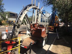
Denver Public Works decided to construct the greenway drainage channel from the east end and move west. That decision required Xcel Energy to begin its relocation project with the North California 9542 circuit since drainage construction would affect it first. Designers decided to relocate the North California line in a stairstep route south and east of North substation along city streets. Because this route meant the transmission lines would be below residential streets, the workdays and hours that big cable reels could be transported to work sites were limited.
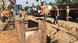
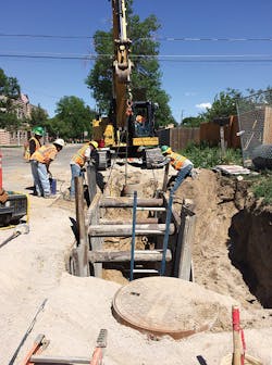
As might be expected on a project of this type, crews encountered the unexpected. Trenching crews found some of the many abandoned or undocumented utilities beneath streets in historic neighborhoods. Because the route could not be changed, the design team created the most efficient underground paths around these obstacles.
Compressed Design Time
For an underground transmission project of this magnitude, the typical time between start of engineering and start of construction is two years. For the North California 9542 transmission line relocation, the time for POWER to perform engineering design was compressed to about four months, so construction could start in mid-March 2017.
To make that schedule manageable, Xcel Energy and POWER broke the project into four civil design phases and two electrical design phases. This enabled field data to be sent to the engineering designers, who focused on one phase of the line work at a time. Then construction work started as design moved on to the next phase.
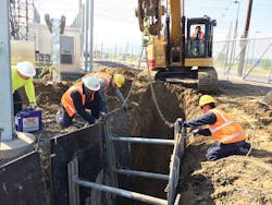
The project employed three crews simultaneously to keep trench work moving on the compressed schedule. This required additional coordination with the city for traffic control and lane closures at three locations instead of just one site. On major streets such as Bruce Randolph Avenue, the city limited work to one crew in the street at a time. Instead of designing for all of Bruce Randolph and having three crews spread out along the street, POWER had to ensure the design was completed for other areas to keep the remaining two crews working.
Underground transmission duct banks require specialized concrete mixes with good heat dissipation properties to increase cable ampacity. With three crews at work at one time, concrete suppliers sometimes scrambled to keep up with the demand for material.
Keeping the project moving required careful scheduling, coordination and construction meetings with Xcel Energy’s engineering staff and construction crews, POWER staff and contractors. Open communication, with lots of emails and Skype conference calls, proved essential. POWER’s designers maintained extensive contact with crews in the field to stay informed of any issues they experienced. The designers then used those insights to improve the design on the next phase.
Critical Deadlines Met
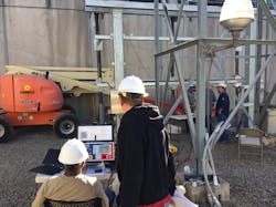
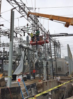
POWER served as the project engineer for the design and construction of the new foundations and termination structures needed for the conversion. The work took place in an exceptionally narrow station space that did not allow for truck traffic. The new termination structure in the California substation had to be hoisted over the substation’s wall. Construction support and constant interaction with the field crew played a big part in the successful conversion.
Despite the challenges presented by the demanding schedule and congested urban environment, Xcel Energy and POWER met Denver Public Works’ critical deadline for relocating the underground lines, which enabled the stormwater channel project to move ahead as planned.
For more information:
POWER | www.powereng.com
Xcel Energy | www.xcelenergy.com
