Fingrid’s Asset Care Reaches the Next Level
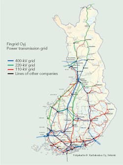
Fingrid Oyj is responsible for the main transmission system in Finland. The system comprises approximately 14,000 km (8,700 miles) of transmission lines and 113 substations, operating at voltages from 110 kV to 400 kV, which are mainly equipped with air-insulated switchgear.
The maintenance concept at Fingrid is based on outsourcing while retaining technical expertise in the form of centralized equipment specialists and regional specialists for main asset classes. Maintenance work is purchased from suppliers through competitive bidding, with contracts divided into long-term for basic maintenance and short-term for specialized maintenance.
Fingrid collects a variety of information about the transmission grid from several databases that is used by grid-management specialists. The root task is to verify that components are in good condition and that condition- or time-based maintenance activities proceed as planned. The long-term target is to discover the weak-performing assets and hidden defects early enough to allow repairs or replacement investments to be undertaken at an optimal time. To fulfill this objective, a tool was developed to process the large volume of data in a way that improved visualization and automatic early-stage notifications.
Condition Monitoring
The target for the condition-monitoring system (CMS) was to give easy access to on-line historical data for maintenance purposes and to process the off-line maintenance data. The objective was a common tool for maintenance specialists and control room personnel to monitor assets. The function of the system required was to provide a smart overview of the status of equipment, generate alarms, display relevant trends and analyze data on user demand. The project was based on existing OSIsoft PI system, resulting in a ready-to-use CMS within eight months of startup.
System Overview
The CMS comprises several components. Grid power flows, voltages, currents, SF6 pressures and transformer gas development come from supervisory control and data acquisition (SCADA) and on-line condition-monitoring devices. Nominal values, manufacturing date, device defects, defect-severity categorizing and measurements from device service actions come from the off-line asset-management system.
Redundant PI servers store incoming on-line data, enabling the use of data either directly or indirectly. The PI Server processes both on-line and off-line measurements, which are combined with the asset framework so that measurement tags are linked with a corresponding asset element. The asset framework is accessible from all PI software, which speeds up searching for tags related to a specific asset.
The asset framework also provides displays for each element, whereby only one display is needed for each substation asset (for example, one transformer display, one circuit breaker and so forth). When users change from transformer 1 to transformer 2, the display stays same but the values are updated.
SF6 On-Line Monitoring
European Union regulations have become more stringent concerning the use of fluorinated gases and monitoring of their emissions. The implementation of SF6 on-line monitoring supports the gas management and improves the monitoring of the gas levels in the switchgear. The system uses a milliamp output sensor in the gas compartment’s back-pressure valve. The signal is scaled and transferred to the SCADA system. The milliamp output is proportional to the SF6 density in the gas compartment. Density changes are recorded by the sensor output and noted immediately in the monitoring system. To have more user-friendly measures, density values are converted to temperature-compensated pressures.
The system is now a common practice for all the new SF6 installations and proves to be a powerful method for analyzing the gas compartments tightness levels in the Nordic environment with high temperature variations.
Alarm Levels
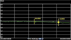
Fingrid monitors SF6 gas leakages using the new CMS. In addition to continuous measurements, spaced measurements are recorded daily at 2 a.m. This ensures exclusion of all minor measurement disturbances such as direct sunlight on the sensor. Fingrid uses two notification rules. The first rule is designed to monitor fast leaks while the second is for slow and small leaks, which are difficult to identify.
- Rule 1: Fast alarm (red alarm). This rule triggers when continuous pressure measurements fall below the nominal value, which is modeled on a 90-day average of the pressure measurement. The temperature-compensated pressure fluctuates naturally within the sensor-accuracy class, thus the tolerance on the limit value has to be sufficient to avoid unnecessary alarms but small enough to give early warnings when there is a gas leak. At present, Fingrid uses a limit value of 0.30 bar (4.4 psi).
- Rule 2: Slope of the regression line (yellow notification). Fingrid’s approach to very small gas leaks not detected by the first rule is to monitor the slope of the regression line of the temperature-compensated pressure measurement. The slope value is robust enough for noise but sensitive enough to register small leaks. Based on experience, Fingrid uses a limit value of -0.0004 bar (0.0058 psi)/day.
System Experience
The commissioning of this gas on-line monitoring system revealed that a relatively high percentage of the circuit breakers purchased between 2009 and 2012 failed to comply with the International Electrotechnical Commission (IEC) tolerances for SF6 gas leakage. In general, the leakage rates were slow, activating Fingrid’s second rule. A root-cause analysis of each incident identified obvious component, manufacturing or installation defects. Bringing failures to the attention of individual manufacturers has exerted pressure for manufacturing changes and an extended after-delivery guarantee period.
Leakage monitoring is based on group overviews and single device views, which also can provide additional information. Each device’s green, yellow and red indicators all feed to provide an overview of the situation. The single circuit breaker view shows the leakage trend in each phase, the present temperature-compensated pressure values and the calculated value of the leakage trend slope. In addition, system voltage and real-time circuit breaker current can be displayed in the window together with information of the operation amount during a preset time period.
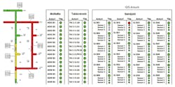
For a gas-insulated substation (GIS), the leakage monitoring view is based on the summary view, which provides an overall summary for all the substations and gas compartments. In addition, each GIS substation has its own graphical view for gas compartment status with red, yellow and green indicators, and current gas pressures.
Health Index Analysis
Fingrid is making a major investment in its transmission system. New substations and transmission lines are under construction to increase the transmission network capacity in advance of new generation from planned wind power and nuclear power plants. Coincidentally, the substation infrastructure built in the 1970s is nearing end-of-life status and should be refurbished during the same time period.
From a grid-management perspective, it would be beneficial to verify the correlation between older substations and components to identify the components in terms of their risk status. Then the higher-risk substations or component investments could be scheduled at an earlier stage in the overall plan or an intensified maintenance focus could be an alternative.
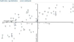
This health index identifies the priority in terms of additional maintenance or need of renewal. An index of this kind is essential when the population of components is large. The idea of a switchgear health index is to determine a value for every device and then combine these values to evaluate the complete switchyard. The index calculations are based on the defect statistics and weighting factors that highlight the components more clearly (for example, according to reduced manufacturer support, high value of operations, overaged components or other predefined properties).
The general-population defect frequency identifies the balanced, or average, defect history for a specific asset. The defect frequency is calculated for each and every asset location, and identifies the actual recorded defect history for each location. Calculating these two different frequencies together generates an artificial defect index. This index identifies assets from different perspectives.
Population Analysis
Where the defect frequency of an asset population is high, the sum value index will be noted, although the actual asset location would not have experienced as many defects as the rest of the population. If the actual asset location has been subject to a high defect rate and the asset population is in good condition in general, this will be noted. Having high value in both approaches will highlight these devices clearly.
This artificial defect index is the core of the system. This index can be adjusted with specific defect-frequency factors. If the general-population defect frequency is more important, it can be weighted with a free-choice value, like 1.5, giving a 50% higher approach in the calculation. On the other hand, the location-specific frequency can be reduced with another factor, like 70% of the calculated defect rate. When major- or minor-classified defects need to have greater priority, these values can be highlighted with additional weighting factors.
The weighted index is fed into the additional calculation. At this stage, the calculated index will get specific additional factors based on the known manufacturer support, number of operations and maintenance intervals. Each weighting category can consist of several subparameters (for example, breaker operations <2,000 factor 1; 2,000 to 3,999 operations factor 1.25; >4,000 operations factor 1.7; >5,000 operations factor 2).
These results can be presented and summarized in several ways:
- Overall substation switching assets index distribution diagram
- Main report, informing the visual status of the switching devices and also providing information on the average age and standard age deviation within the substation group
- Detailed substation view with defect history and defect-severity categorizing in each asset location
- Identification of the top 50 worst assets in predefined categories, such as bays, reactor breakers and disconnectors.
The main benefit of the system is a tool approach that offers the possibility for the user to update all of these views and visualize the effects by easily changing the free-choice factors and source variables. This analysis can strengthen already known component weaknesses but also may point out additional needs for further clarification from different perspectives.
Transformer Monitoring
During the past few years, on-line transformer monitoring devices have become more common. Furthermore, the SCADA system can offer transformer on-line information that needs to be reviewed by the same monitoring analysis.
Fingrid’s new grid transformers will be equipped with on-line oil analyzers designed to record and analyze dissolved gases at frequent daily intervals. A retrofit pilot installation on an existing transformer took place in 2009, and Fingrid now has 18 dissolved gas on-line analyzers in commission. All have direct Ethernet connection to the PI history database via fiber connections, and in the future, Fingrid will have 70 grid transformers equipped with devices to monitor and analyze moisture, and identify the presence of three to eight dissolved gases.
Transformer monitoring on-line and off-line data is easy to connect into PI history database for display on the CMS. This gives maintenance specialists the flexibility to select the on-line monitoring device for individual transformers and assess the unit’s on-line status using one software application.
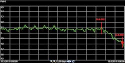
The particular benefit of this CMS system became apparent to Fingrid in May 2012 when an increasing oil-gas ratio was noted on a transformer. The CMS detected the adverse correlation between two SCADA system on-line measurements, the low-voltage current and the oil-gas ratio, and confirmed with diagnostics measurements that gave Fingrid time to react and take remedial action.
Future Development
The CMS has established its value and support for the asset-management personnel with fast data visualization, comparison possibilities and status information. The CMS functions are not limited by the software, and the end users can employ their knowledge to reconfigure the system.
As the transmission assets are continually changing, the CMS system asset hierarchy must be kept updated. In addition, a wide range of development possibilities exists for the system, such as implementing new alarm triggers for transformers and expanding the health index philosophy for other system assets. Increased information on substations and the collection of more off-line data from the asset-management system will be available for CMS analysis. Also, system interfaces will create new possibilities to connect more types of monitoring devices once they are evaluated and approved.
Tuomas Laitinen ([email protected]) received a MS degree in power systems and high-voltage engineering from the Helsinki University of Technology in 2001. His work covers project management for maintenance and retrofit projects, life-cycle responsibility including type acceptances, and maintenance program planning for switching devices, gas-insulated substations and SF6 gas.
Juha Mertanen ([email protected]) received a MS degree in power systems and high-voltage engineering from the Tampere University of Technology in 2005. His work covers project management for maintenance and retrofit projects, responsibilities for substation condition-monitoring systems, substation retrofit and refurbishment coordination, and substation earthing.
Kimmo Nepola ([email protected]) received a MS degree in power systems and high-voltage engineering from the Aalto University in 2013. His work covers project management for maintenance and retrofit projects, development of condition-monitoring systems and techniques, and R&D in asset management.
Companies mentioned:
Fingrid Oyj | www.fingrid.fi
International Electrotechnical Commission | www.iec.ch

