Crossing The Delaware With PECO
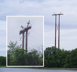
In the fall of 2013, PECO Energy Corp. (formerly the Philadelphia Electric Co.) embarked on an exciting challenge to develop a design for a 300-foot (91 m) tall free-standing H-Frame structure required to support a 230-kV single-circuit transmission line span crossing the Delaware River. While tall H-Frame structures can have some unusual and complex design considerations, they can become even more so when you add an intricate catwalk and a fall protection system.
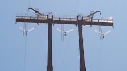
The transmission structure would span across the river and tie in with another utility on the other side. The proposed design, presented to Meyer Utility Structures to come up with, would be an H-Frame configuration with climbing and resting platforms on the legs. In addition, PECO requested an OSHA (Occupation Safety and Health Administration)-compliant catwalk that would extend the entire length of the 78-foot (24 m) crossarm at a height of approximately 290 feet (88 m) above ground.
Design Challenges
To properly support a large catwalk, a crossarm diameter of 35 inches (89 cm) was needed. The top diameter of each of the structure legs was dictated by the diameter of the crossarm. Using a top diameter of 35 inches (89 cm) resulted in an efficient design, however the deflections were too high to allow fixed catwalk connections. Cross-bracing was added to reduce the deflections, and a considerable amount of time was spent trying to optimize both the size and location of the bracing. The addition of the cross-bracing resulted in high axial loads in the braces that in turn resulted in unacceptable stresses in the tower leg. Several iterations were needed to finalize the design.
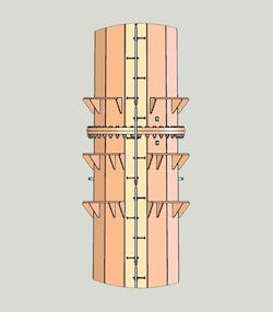
Resting/working platforms were located at each flange connection. The original design concept called for climbing cages. However, with close and continual coordination between the designer, the customer, and the fall protection vendor, Meyer Utility Structures was able to eliminate the cages by using a fall protection system. The fall protection vendor worked directly with PECO to ensure the proposed system would satisfy their requirements. An upper fall protection attachment pull-off plate was added to the fixed ladder and designed to resist a 5,000 pound (22,241 N) static load.
Additionally, a bolt-on plate assembly, provided by the fall protection vendor, offset the cable from the face of the climbing ladders and allowed for easier transitions around flange connections. There were additional intermediate cable attachments down the length of the structure shaft as well as bottom termination brackets. In close collaboration with the fall protection vendor, pull-off plates were provided at each of the cable attachment locations.
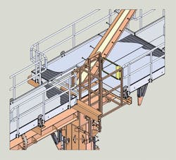
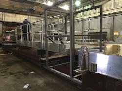
The 78-foot (24 m) OSHA-compliant catwalk was designed by an outside vendor in close cooperation with the manufacturer. Meyer decided to use aluminum for the catwalk due to the significant weight savings vs. steel (approximately 1.2 kips (544 kg) per section). The catwalk vendor was chosen after a vetting process that included a plant visit. To help mediate the effect of cross arm deflections the catwalk was fabricated in 10-foot (3 m) sections and utilized slots that would allow relative movement between the crossarm and the catwalk.
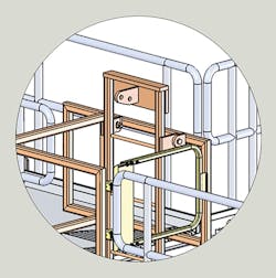
Solid models of the structure and the proposed catwalk were created and shared with the catwalk vendor. This allowed any potential fit-up issues to be resolved prior to fabrication. Angles were welded to the crossarm to provide the means of securely attaching the catwalk. Stainless steel hardware was used to address potential corrosion issues that might result from the use of dissimilar metals. This concern was further mitigated by providing a corrosion protection coating between the aluminum catwalk and the attachment angles. Several options were explored concerning the transition from the structure shaft to the catwalk. A fixed ladder was designed to allow easy access to the catwalk through a gate in the handrail.
A steel cage was used to surround the fixed ladder and provide a more secure transition from the tower leg to the catwalk. Additional provisions were required to allow easy access to the ladder rails on the cross arm. Removable handrail sections were provided above each of the conductor locations. The static peaks attached to the cross arm were sloped outward to provide proper shielding of the conductors. The sloping peaks posed a potential clearance problem when utilizing the catwalk. Therefore, the width of the catwalk was increased to 10 feet (3 m) at these two locations to allow enough room for workers to access the entire catwalk comfortably.
In order to safely access the FAA required lighting at the top of the structure, platforms were also installed on the static peaks. Additionally, to ensure proper assembly in the field, the plant assembled the crossarm and attached all of the catwalk sections to it. Removable handrail sections were provided above each of the conductor locations.
Field Assembly
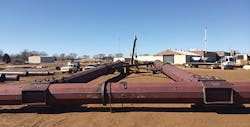
PECO expressed concerns about fit-up issues in the field with assembly 300 feet in the air. To ensure smooth assembly on-site, the structure was pre-fit at the manufacturing plant before shipping. The pre-fit included fully assembling the catwalk and attaching it to the crossarm. The plant followed a specific sequence during the assembly that was shared with the customer to help with the field installation. Lifting points were established by the catwalk vendor for each catwalk section. Some issues were encountered during the field assembly phase of the project, including difficulty installing the flange bolts; these were quickly resolved, and Meyer Utilities shared additional assembly recommendations with the customer to assist in the erection.
A Successful Completion
The end result was a successful project for PECO, particularly in reference to integrating the functionality of the catwalk with the structure performance. The design of the transition zone with the fixed ladder made access to the catwalk superior to designs PECO has seen on other projects. Meyer Utilities was able to work directly with the catwalk vendor and fall protection vendor, as well as the customer throughout the project. The use of these direct lines of communication and teamwork allowed issues to be resolved quickly and to the satisfaction of all concerned. Due to the close and continual col- laboration between multiple entities, the project was completed on time and on budget.
About the Author
Guy Faries
Guy Faries, P.E., began his engineering career in 1997 at Thomas and Betts, designing steel transmission structures. Faries then worked for Aluma-Form. After eight years, he returned to Thomas and Betts continuing to design steel structures. Faries developed new products as well as improving existing ones. Presently, he is working at Meyer Utility Structures as an engineering manager, overseeing the design of transmission structures while continuing to develop new products.
Kalpesh Patel
Kalpesh Patel, P.E., has more than 17 years of experience in design and project management of steel structures projects for transmission industry. Patel is working at Meyer Utility Structures as a value stream manager, leading a team of engineers, project managers and engineering manager responsible for proposal development.
