High Voltage AC Transmission Line Design: NESC 5-mA Rule Considerations
For voltages exceeding 98 kV ac to ground, either the clearances shall be increased or the electric field, or the effects thereof, shall be reduced by other means as required to limit the steady-state current due to electrostatic effects to 5-mA if the largest anticipated truck, vehicle, or equipment under the line were short-circuited to ground. The size of the anticipated truck, vehicle, or equipment used to determine these clearances may be less than but need not be greater than that limited by federal, state, or local regulations governing the area under the line. For this determination, the conductors shall be at a final sag at 50 °C (120 °F).
This article provides basic theoretical background about the 5-mA Rule, historical context, and practical considerations when applying the rule in the design of overhead transmission lines.
Basic Theory
Propagation of energy on AC transmission lines involves time varying electric and magnetic fields. Most of the energy is transmitted longitudinally between the terminal stations or lost to heat in wire resistance (I2R losses). However, energy can also couple to nearby objects through the electric and magnetic fields. The 5-mA Rule arises because of coupling via the electric field. Recall that a capacitor consists of two electrodes separated by a dielectric. From this basic description we observe that capacitance exists between transmission line conductors and between each transmission line conductor and ground (zero-potential conductive earth). Air serves as the dielectric.
Due to the large spacing between electrodes, the amount of capacitance and corresponding current to ground are normally extremely small. However, if a conductive object positioned between earth and the transmission conductors is connected to ground, it becomes part of the zero-potential electrode of the capacitive circuit. Its closer proximity to the conductors means that the corresponding capacitance per area is higher than of the earth. In the case of the earth, any capacitive current that flows is distributed over a large area. However, in the case of the grounded object, all the capacitive current flows through the path that connects it to ground.
Fig. 2 is an equivalent per-phase circuit of the example shown in Fig. 1. The system can be represented by a capacitor between the transmission line and the vehicle and another between the vehicle and ground. If a person standing on the ground touches the vehicle, they become a path to ground for the capacitive current (electrostatic contact current). Contact current tends to increase with the area of the vehicle (an exception is discussed later). It is important to note that the contact current to ground is a steady-state AC current. It would be incorrect to describe it as a temporary static discharge. The term electrostatic applies because the currents are small and the effect of the time varying magnetic field on the electric field (Maxwell-Faraday equation) is negligible.
Since the 5-mA Rule specifies the current of interest as that of a short circuit from the object to ground, the impedance of the person and the capacitance from the object to ground are not of interest. Detailed calculations are beyond the scope of this article, but at a high-level they involve determining or estimating the capacitance between the transmission line and the vehicle or object. The EPRI Red Book estimates the effective charge collecting area using a cuboid shape [2]. Detailed representations of the vehicle or object can be done with charge simulation or finite element methods [3]. Electromagnetic reciprocity theory can also be applied to solve these types of problems [4], [5].
Why 5-mA?
The 5-mA rule was being considered for inclusion in the National Electrical Safety Code as early as 1974 [6]. The 2017 NESC handbook [7] references a report by the Naval Medical Research Institute which summarized research since the 1930s on the biological effects of electrical exposure [8]. Significant study was completed during that time due to a spate of accidents in the early days of widespread electrical use [9]. Various researchers concluded that 5-mA was a reasonable safety limit. In 1984, Banks and Vinh provided a thorough review of the basis of the 5-mA threshold and concluded that this threshold is very defensible for occupational exposure, but less defensible for vulnerable individuals such as children [9].
Key experimental data was collected by exposing volunteers to increasing levels of 60 Hz current to establish a "let-go" threshold. This is the maximum current at which a person is still able to voluntarily release an electrode they have grasped. Releasing the electrode may not be possible above the let-go threshold due to muscle contractions. Fig. 3 and Table 1 summarize example experimental data listed in [6].
Note that the 5-mA threshold may in fact be painful but is below the statistical let-go threshold for adults. Also, it is important to be aware that a line can be compliant with the 5-mA Rule, but still have contact currents higher than 5-mA. This is due to the statement in the rule which connects the threshold to a specific temperature and sag condition. If conductor temperature increases above 50 °C, the greater sag could feasibly result in contact current above 5-mA.
The International Commission on Non-Ionizing Radiation Protection (ICNIRP) recommends the thresholds in Table 2 based on perception in adults and children [10]. ICNIRP levels are not typically used as a limit for high voltage transmission line design. Researchers have suggested that the higher 5-mA threshold is justifiable by the fact that such human exposures are rare [9].
Study Considerations
The remainder of this article provides examples that illustrate transmission line design 5-mA Rule study considerations. All examples were prepared using the POLARIS-EMF software by Electric Utility Design Tools (www.electricutilitytools.com). The results from these examples are intended to be realistic, but illustrative. Therefore, these results should not be used as a substitute for analysis of specific design cases.
Vehicle or Object Size/Orientation
The NESC clause is somewhat vague about vehicle or object size. While it does mention the “the largest anticipated truck, vehicle, or equipment” it also indicates that the selected vehicle size can be less than what is specified by government regulations. In the U.S., state
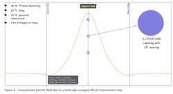
Transportation Departments websites are a good starting place to find size limit regulations. Engineers must evaluate the environment of the route and apply judgment to determine the vehicle or object size(s) to consider in design. While the clause implies that the largest vehicle is the worst case, this is not always true. Consider the example in Fig. 4.
A vertically arranged 345 kV transmission line (structure not shown) has a 35-foot minimum ground clearance.
The maximum electric field within the right-of-way is 5.37 kV/m (1.637 kV/ft). Using software, different lengths of semi tractor-trailer combinations are swept through the right-of-way and the maximum electrostatic contact current for each vehicle length is determined. Results are listed in Table 3 and include parallel and perpendicular vehicle orientations with respect to the line conductors. Note that all perpendicular cases are within the 5-mA limit while some of the parallel cases substantially exceed it. Column three in the table indicates the increase in height needed to bring the respective parallel cases into compliance.
*All vehicle widths, heights, and ground clearances are identical.
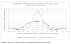
Note that for the perpendicular orientation, the largest vehicle does not produce the maximum short circuit contact current. In this orientation the vehicles extend beyond the region of maximum electric field. At some point, as length increases, the reduction in average electric field over the length of the vehicle overcomes the effect of increasing surface area and contact current decreases. However, with the parallel orientation, the vehicle is almost entirely under the region of maximum field and contact current increase is approximately linear with respect to vehicle size.
The results in Table 3 illustrate the benefit of modeling the electric field variation over the surface of a vehicle or object. A simple approach sometimes used in industry is to calculate the maximum electric field and then apply that maximum to a rudimentary representation of the vehicle or object. This approach typically results in higher than actual contact currents and possible excessive impacts to structure height. In the case of Table 3, the simple approach would produce results slightly higher than those of the parallel case and would not distinguish between vehicle orientations.
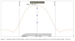
Fig. 5 shows a plot of contact current as a function of vehicle position in the right-of-way for the perpendicular case with the 122.8-foot vehicle. The plot includes the vehicle for visual scale and is at the approximate location under the line corresponding to maximum contact current. Asymmetry in the plot is due to front-to-back asymmetry of the vehicle. Fig. 6 compares perpendicular and parallel results for the same 122.8-foot vehicle case.
Engineers can consider natural barriers which restrict position and orientation. For example, a road may run parallel to a transmission line, but if the shoulder or other barrier restricts a vehicle’s encroachment into the right-of-way then contact currents may be lower than the maximum obtained without such restriction. While it may seem unlikely for a twin trailer semi-tractor to be oriented parallel to and directly underneath a line, the author is aware of multiple situations involving narrow easements and agricultural regions where such a configuration was possible.
Buildings
Buildings have a large surface area. Even if located outside the right-of-way, significant electrostatically induced current could be present if the building or portions of the building are metal-clad or have conductive paint. Typically, a building’s foundations will have good contact to ground, but if the metal cladding is attached to a wood frame, then an insulated condition may exist. Grounding insulated cladding can mitigate the problem, but studies are useful to show contact current severity if the ground is damaged. If severe enough, multiple grounds may be warranted. Since most buildings are located outside the right-of-way, 5-mA rule compliance is often not a problem. However, since buildings are frequented by people, most utilities choose to mitigate buildings for annoyance/perception.
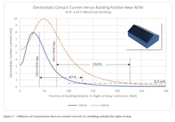
Consider the two examples in Fig. 7. A metal-clad building the size of a moderate home or shop is placed near the right-of-way of a 230 kV transmission line and that of a 500 kV transmission line, respectively. The long axis of the building is parallel to the conductors. The plot shows contact current as a function of the building’s distance from the corridor centerline. Using the ICNIRP general public exposure limit of 0.5-mA as a threshold (Table 2), it is evident that contact currents could be a perception issue well outside the right-of-way.
Mitigation
In addition to conductor height adjustment and grounding the object, any adjustment that reduces electric field strength near ground level will reduce contact currents. Examples include:
Use bundle and phase configurations that provide better field cancellation near ground level.
Install shield wires below phase conductors [11].
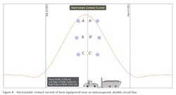
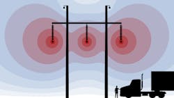
Consider the 345 kV system in Fig 8. Two circuits are installed vertically on steel pole structures (not shown) over agricultural land. The largest vehicle is assumed to be a tractor with grain cart (approximately seventy feet total length). Phases A and A’ are assumed to have the same magnitude and angle and are each placed in the top position. Likewise, the other phase pairs are respectively assumed to be in-phase. The maximum contact current for a parallel orientation is about 6.5-mA. To mitigate this with a change in height requires ten additional feet of clearance. This may not be a significant cost increase for a single span, but if the route is over agricultural land, many structures could be affected and the increased cost to towers and foundations could be significant.
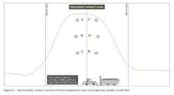
Next, the model was adjusted so that the second circuit is transposed to provide some electric field cancellation near ground (Fig. 9). The result is a reduction of the contact current by almost a factor of two (≈3.3 mA). Taking advantage of field cancellation can be quite effective. However, it is especially important that the phase angle relationship between the two circuits is known. Field cancellation under all operating conditions cannot be relied upon if the phase angle difference drifts.
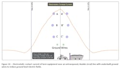
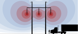
Next, consider the un-transposed case of Fig. 10. Here shield wires are installed twenty feet below the phase conductors. The contact current is reduced to within limits. The horizontal positions (±8 ft.) of the shield wires were optimized through software iterations to minimize contact current. Using underbuilt shield wires may still require additional height for ground clearance since they must be placed far enough from each other and the phase conductors to meet applicable electrical clearances and mechanical considerations such as galloping. However, the increase in structure height is not expected to be as large as that required to mitigate the un-transposed case without underbuilt shield wires.
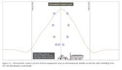
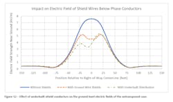
Similar benefit can be obtained by taking advantage of the shielding effects of distribution or sub-transmission under-build. Fig. 11 shows results with the same transmission configuration as Fig. 10, but with a 34.5 kV distribution under-build. The ground level electric field from distribution level circuits is weak so the conductors, despite being energized, still provide a shielding effect. Fig. 12 compares the electric field near ground level for the un-transposed case without shielding to the two cases with shielding below the 345 kV circuits.
Conclusions
Designing transmission lines to limit risk to humans includes compliance with the NESC 5-mA rule. The examples above illustrate various considerations when assessing electrostatic contact current of transmission lines. Vehicle or object orientation and position under the line can have a significant impact on contact current results. The largest vehicle under the line tends to be the worst case, but not always; particularly when the vehicle is oriented perpendicular to the conductors. Where possible, taking advantage of vehicle or object position constraints can minimize calculated contact currents and possibly save on structure costs.
The high probability of human exposure near metal-clad buildings increases the need to consider mitigating for perception rather than injury. Due to their large charge collecting area, currents above perception thresholds can be a problem at a significant distance from the right-of-way. Finally, assorted options exist to mitigate contact current issues by reducing electric fields near ground level. These include increasing conductor height, using phase arrangements that provide field cancellation when phase angle relationships are known, and incorporating shielding effects of underbuilt distribution circuits or ground wires.
References
[1] Institute of Electrical and Electronic Engineers, 2017 National Electrical Safety Code(R) (NESC(R)), New York , NY: IEEE, 2017.
[2] EPRI, Transmission Line Reference Book, 345 kV and Above, 2nd ed., Palo Alto, CA: Electric Power Research Institute, 1982.
[3] J. T. Leman and R. E. Schaerer, "Quasielectrostatic Induction on Stationary Vehicles under High Voltage Power Lines," in COMSOL Conference, Boston, MA, 2012.
[4] R. G. Olsen and J. T. Leman, "On Calculating Contact Current for Objects Insulated From the Earth and Immersed in Quasi-static Electric Fields," IEEE Power and Energy Technology Systems Journal, vol. 4, no. 1, 2017.
[5] R. G. Olsen, High Voltage Electromagnetics, Volumes I and II, Second Edition, CreateSpace Independent Publishing, 2018.
[6] Rural Electrification Administration, "Electrostatic and Electromagnetic Effects of Overhead Transmission Lines," United States Department of Agriculture, Washington DC, 1976.
[7] Insitute of Electrical and Electronic Engineers, 2017 National Electrical Safety code (NESC) Handbook, Premier Edition, New York, NY: IEEE, 2017.
[8] J. C. Keesey and F. S. Letcher, Minimum Thresholds for Physiological Responses to Flow of Alternating Electric Current Through the Human Body at Power-Transmission Frequencies, Bethesda, MD: Naval Medical Research Institute, 1969.
[9] R. S. Banks and T. Vinh, "An Assessment of the 5-mA 60 Hz Contact Current Safety Level," IEEE Transactions on Power Apparatus and Systems, Vols. PAS-103, no. 12, 1984.
[10] International Commission on Non-Ionizing Radiation Protection, "ICNIRP Guidelines for Limiting Exposure to Time-Varying Electric and Magnetic Fields (1Hz - 100 kHz)," Health Physics, vol. 99, no. 6, pp. 818-836, 2010.
[11] R. M. Radwan, A. M. Mahdy, M. Abdel-Salam and M. M. Samy, "Electric Field Mitigation under Extra High Voltage Power Lines," n IEEE Transactions on Dielectrics and Electrical Insulation, vol. 20, no. 1, pp. 54-62, 2015.
[12] J. M. Lee, K. S. Pierce, C. A. Spiering, R. D. Stearns and G. VanGinhoven, Electrical and Biological Effects of Transmission Lines, A Review, Portland, OR: Bonneville Power Administration, 1995.
About the Author
Jon Leman
Jon T. Leman ([email protected]) is an electrical engineer with over 20 years of experience in AC and DC overhead and underground transmission line design and power system studies. He is currently the owner and principal engineer of Power Electromagnetics Consulting, PLLC and a partner at Electric Utility Design Tools, LLC, a provider of transmission line design software. Leman earned his Ph.D. degree in electrical and computer engineering from Washington State University and his MSEE and BSEE degrees from the University of Idaho. His technical interests include electromagnetics, power system transients, equipment failure investigation, numerical methods, insulation coordination, and power system planning. The focus of his doctoral research was the application of electromagnetics to optimize high-voltage transmission line design. He is a member of CIGRE and a senior member of IEEE.
Ray Seemiller
Ray Seemiller

![Figure 3: Let-go threshold information from experiments [6]. Figure 3: Let-go threshold information from experiments [6].](https://img.tdworld.com/files/base/ebm/tdworld/image/2022/01/Figure_3.61f1814270c1b.png?auto=format,compress&fit=max&q=45?w=250&width=250)


