Optimizing Steel H-Frame Foundations: Ameren’s Innovative Approach to Pole Embedment Depths
For over a century, wood pole structures have been used to support overhead powerlines. Over time, as the utility industry expanded, the basic wood pole structure has evolved, but regardless of changes in technology or increases in structure loading, some traditional design fundamentals are still widely practiced today. Namely, one rule is the same: how deep structures should be embedded into the ground when using rock backfill. The pole embedment continued to follow the same approach, a percentage of the total pole length plus some constant, generally 2 feet (0.6 m).
For decades, this rule worked well for pole embedment in ordinary soil conditions, but the utility industry is changing. Load growth continues to increase, and other materials such as steel have found their way into the industry. To keep up with load growth, larger structures supporting larger wires are a necessity and traditional rules require change for structures and foundations to be sufficient. The embedded portion of the pole is critical to resist and distribute all loads to the surrounding soil. A century old rule requires more than just principle. It requires evidence that new and existing foundations can sustain loads of the future.
An Unsolved Mystery
Ameren identified several transmission line projects that require the use of steel H-frame structures with traditional direct embed foundations using crushed rock backfill. Steel H-frame style structures were selected to increase reliability and handle future load growth across the Ameren system. This structure type is still relatively new and the utility industry, including Ameren, lacks the decades of experience that conventional wood poles carry, specifically with respect to foundation performance.
Concern grew at Ameren around following the traditional setting depths for H-frames with traditional backfill for a steel H-frame structure. Was it safe to assume steel structures would have the same foundation performance as wood? Ameren’s steel H-frame structure followed the same configuration and framing as their wood structures. However, steel is naturally capable of supporting larger loads.
Foundations need to be strong enough to resist movement and rotation. If the above-grade structure can support much higher loads compared to wood, then the foundation must be modified to also support those loads. Steel surfaces also have a lower side frictional resistance against soil when compared to wood surfaces, which places steel foundations at a disadvantage. The interlocking between wood and rock backfill creates an advantage over steel. Ameren did not want to shy away from using common crushed rock backfill and other materials, including concrete, were not of interest. The approach was to keep the structure similar to wood so that structure and foundation installation, as well as the line hardware would follow the same approach as wood H-frame projects.
Rather than relying on traditional utility best practices or attempting to make improvements to the pole setting depths to meet the newer design, Ameren decided to test the structures. The goal of the testing was understanding more about the foundation’s performance and ultimately a cost-effective solution for pole setting depths. The objective was to find a suitable pole setting depth for steel structures and to test the historical practices of wood structures.
One of the first Ameren projects requiring steel H-frames was set to start construction within 18 months, which provided a fast timeline to develop a testing plan, perform the load tests and implement a design basis. With a bold schedule and a budget in mind, Ameren elected to test four complete H-frame structures to develop a design basis and better understanding for pole setting depths.
Ameren chose to test three steel H-frame structures and one wood H-frame structure. The structure configurations selected for the testing ranged between 80 feet (24.4 m) with one x-brace and 85 feet (25.9) with two x-braces. The team decided to test a range of foundation setting depths, 10% + 2 feet (0.6 m) and 10% + 4 feet (1.2 m).
Foundation depths deeper than 10% + 4 feet (1.2 m) would only be tested if the initial two load tests justified the need. The three steel structure tests would provide enough evidence to develop design parameters while the one wood structure served as a control variable and provided an opportunity to test the century old rule.
Setting the Stage
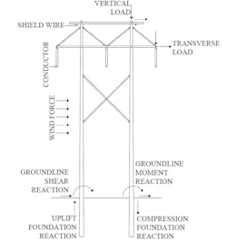
Framed structures or H-frame structures that are longitudinally stable experience their greatest threat when loaded laterally. Large horizontal loads such as wind, that act perpendicular to the supporting structure and attached wires may cause frame rotation and even overturn the foundation out of the ground. The windward pole on an H-frame structure is likely to pullout of the ground if the foundation is not set deep enough or the surrounding soil is too weak.
The National Electric Safety Code (NESC) is the governing body that covers the design and detailing of transmission structures. The NESC provides extreme weather events that structures and wires must be designed for, these may include extreme wind with no ice or extreme wind with ice applied to the wires. Extreme wind pressure with no ice applied to the wires and structures was found to control the loading on a standard H-frame structure.
The Ameren team needed to recreate this extreme wind event in a controlled environment by only installing the complete structure without any wire spans. To accomplish this, maximum horizontal and vertical point loads were calculated using the expected line design parameters such as span length, wire size, wind pressure, and wire weight. The total horizontal and vertical point loads were applied to the wire attachment positions on the test structure, attempting to meet or exceed the expected design loads during the load test.
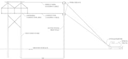
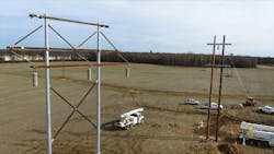
Vertical loads would be applied to each attachment point using constant weights, representing the bare cable weight. Horizontal loads would be applied using a cable controlled by a truck winch; one cable to the shield wire arm position and the other to the conductor arm position. The wire attachment positions on the test structure were located more than 50 feet (15.24 m) above the ground. The project team needed an engineering solution to safely apply these horizontal loads in a controlled environment.
To create a pure horizontal load where the wind is loaded on the wires, the team decided to use a wood prop-structure to redirect the wire from the winch up to the test structure. At the prop-structure, the cable was supported by a swinging wire sheave to create equal tension on either side of the prop-structure.
The cable would leave the prop structure at an angle to the winch and would also leave the prop structure horizontally to the test structure. The applied cable loads were measured at the truck winch. Ameren’s contractor surveyed the structure at the pole tops and groundline to measure pole displacement during each load increment.
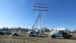
To execute this load test, Ameren first needed to find a large enough property that could host the load testing and have ideal geotechnical properties. Ameren had recently purchased 10 acres (4.05 Hectares) of land in south central Illinois to construct a future substation; the timing couldn’t have been any better.
Soil information at this site was ideal, representing the common soil types found throughout Ameren service territory. The Ameren team elected to use this location for the testing and planned to perform the first test in December 2019.
Hold Your Breath
It was a frigid morning in south central Illinois when the project team first embarked to the testing site to witness something either remarkable or disappointing. The project team had one shot to get this right and to determine an efficient design for the steel H-frame projects to stay on schedule. The team recognized that one structure should be installed and tested at a time. This ensured that changes or modifications to the remaining tests could be made with the testing setups, foundation setting depths, and applied loads.
The first structure was installed, and testing began on one of the steel H-frame structures with the team in attendance to watch. As the final load increment was applied, the structure held its own, hardly moving out of the ground. The first structure was a huge success, proving that a reasonable setting depth can be achieved for the steel H-frame structures with crushed rock backfill.
Following the completion of the first structure, the single wood frame was then installed and tested to the golden rule of 10% + 2 feet (0.6 m). During the wood H-frame load test, the applied loads were increased in increments to reach complete structure failure while the foundation remained in the ground, hardly any movement. The structure failed at the compression x-brace, which was anticipated.
The wood H-frame test was a success to the golden rule and the applied loads; the results acknowledge decades of successful wood frames installed while providing a path forward for future wood structure projects. The remaining two steel H-frame structures were then installed and tested, with the results reinforcing the initial two tests and providing consistent data points for the study.
A New Age
Ameren was fortunate enough to test four different structures to determine the impact from varying setting depth, structure material, and number of X-braces. Perhaps the most important comparison from the study revolves around the difference between test structures one and three.
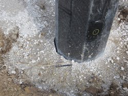
With these two tests, Ameren studied the direct impact of setting a pole 2 feet (0.6 m) deeper than the golden rule of 10% + 2 feet (0.6 m). Under the same applied loads, 2 additional feet (0.6 m) of embedment demonstrated a decrease in groundline lateral displacement by approximately 60 %. Additionally, 2 additional feet (0.6 m) of embedment demonstrated a decrease in vertical uplift movement on the windward pole by approximately 50%.
These results are of important significance, because not only did both structures meet the foundation criteria at maximum loads but going 2 feet (0.6 m) deeper provides flexibility and variation in design. The results provided the project team with knowledge to determine a new design basis for future projects, also generating a cost-effective design that still carries some flexibility for project risks.
The full-scale load tests were not only a success but exceeded Ameren expectations. The Ameren team had many predictions on how each structure would perform, whether the golden rule of 10% + 2 feet (0.6 m) would hold or if going deeper would be needed.
The results suggest that installing direct embed steel H-frames at an embedment of 10 % + 4 feet (1.2 m) is effective under similar soil, backfill and loading conditions. It also provides flexibility in the structure performance. Similarly, wood H-frame structures are effective at an embedment of 10 % + 2 feet (0.6 m) under the same conclusion. Steel H-frame structures will be the design of the future; they provide increased reliability, benefit line construction and they can handle future load growth needs.
About the Author
George Nugent
George Nugent, PE, ([email protected]) Is a transmission line design engineer at Ameren in St. Louis, Missouri. He has over nine years of experience in the power industry and is a licensed professional engineer in the state of Missouri. Currently he leads transmission line engineering projects with voltages between 138kV-345kV. Nugent graduated Magna Cum Laude from Missouri University of Science & Technology with a Bachelor of Science degree in Civil Engineering.
