Overcoming Construction Challenges: How Innovative Engineering Powered the 180-Mile Badger Coulee Transmission Project
Building a 345 kV (kilovolt) transmission line from Holmen, Wisconsin to Middleton, Wisconsin was a study in overcoming some unique and interesting challenges throughout its 180 mile (289.7 km) length. It took eight and a half years from project kickoff to its completion. One of the largest obstacles was the construction of the transmission line adjacent to a major interstate highway for approximately 100 miles (160.9 km). There was also the challenge of a 2,200 ft (670.9 km) long-span river crossing. If that wasn’t enough, the terrain varied considerably from low-lying lands of south-central Wisconsin to the coulee regions of western Wisconsin.
In addition, there was a need for an array of foundation types. Design considerations required the heavy lifting helicopter construction methods be fine-tuned along the right-of-way. There were even difficulties encountered along the interstate highway needing special considerations. Surprises abounded from unexpected areas like railroad signal interference and fiber optic cable installations encountering induced voltages associated with the parallel transmission line.
Wisconsin Department of Transportation (WisDOT) Permitting & Coordination
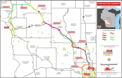
The Badger Coulee transmission line was designed and constructed in eight segments. Each segment had specific and varied challenges, but segments two through six follow a sizable portion of the interstate system. This required a significant amount of WisDOT permitting, which consisted of permits for use of the right-of-way, for placement of transmission line facilities, temporary road and shoulder closures, and performance of the construction work. Early coordination with WisDOT allowed the engineering team to incorporate WisDOT comments, concerns, and future roadway projects into the design of the transmission line.
When working with DOTs, engineering teams should expect a thorough review. DOTs look for adherence of their criteria and the placement of permanent structures. Topics such as clear zones, future expansion projects, road maintenance, bridge clearance, speed, and signage considerations are critical when approving the right-of-way permits, but that’s not all.
Another challenge was stringing the lines parallel to and over the interstate. Using a helicopter introduced a risk of dropping a rope or an emergency landing of the helicopter into travel lanes of the interstate. To help eliminate this risk, the design of the structures was made such that the conductors were arranged on the non-roadside as often as possible, thus reducing the need to fly the helicopter over the WisDOT right-of-way. Shoulder closures were required, but it’s important to minimize closures due to high traffic volumes and public use.
Stringing over the interstate is a highly coordinated activity requiring the closure of interstate lanes. They could not be open during stringing for the public’s safety. The designs of the structures and wire pulls needed to take into account the time it takes for the crews to perform the work. That, however, was not the consideration when it came to topography.
Terrain Variation
Terrain drove design and construction decisions throughout the different segments. The terrain was more docile in the southern portion of the project compared to that of the more varying northern section. This necessitated different structure and foundation designs, which required different equipment to install them.
The design and construction strategies in the southern portion of the project used more traditional methods for foundation, structure, and wire installation. Direct embed and reinforced concrete foundations were used in the southern portion of the project as access to structure locations could be easily made by any size drill rig and concrete truck. Structures could be set via traditional crane methods and wire could be strung using traditional methods.
In the northern segments (Segments five, seven and eight) of the project, numerous foundation and structure locations could not be reached by the same equipment that was used in the southern segments. The terrain in these segments drove construction and design decisions such as setting structures with heavy lift helicopters and use of micropile foundations.
Structure Configurations
Multiple structure configurations were required to meet economical design, permitting requirements, and fit within project constraints. The project made a concerted effort to use the same hardware assemblies across the project. Using the same V-string, angle and dead-end hardware assemblies on the various structure configurations reduced the chance of installing the wrong hardware and simplified material management.
The 180-mile (289.7 km) corridor contained multiple circuit configurations. There were approximately 116 miles (186.7 km) of single circuit line, 63 miles (101.4 km) of double circuit line, and 1 mile (1.6 km) of triple circuit line. In addition, there were a total of seven different circuits attached to the mainline throughout different locations of the project. The voltages ranged from 69 kV to 345 kV. This was required by Wisconsin statutes that prioritize the use of existing utility corridors for new transmission lines.
The triple circuit section was required because the CAPX2020 project was constructing a double circuit 345/161 kV line in the same vicinity as segment eight of the project. Due to the congested nature of the area, it was determined that both projects should be co-located for a 1 mile (1.6 km) section.
Also, the ordered routes for the two projects crossed in two locations. To avoid multiple crossings of the 345 kV lines, a plan was developed where the Badger Coulee project would build on the approved project corridor and then the two projects would transfer assets between where each crossing would have occurred. These “un-crossings” eliminated the need for multiple 345 kV line crossings.
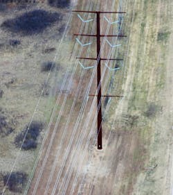
In addition to the multi-circuit configurations, there were single pole (delta and vertical), H-Frame, and three-pole structures. The H-Frame structures were used to reduce the risk of avian collisions by reducing the number of wire zones from three to two and the structures were significantly lower to the ground.
Long Span River Crossing
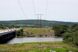
In segment two of the project, a 2,200 ft. (670.6 m) crossing of the Wisconsin River was required. One of the main design challenges for a span of this length is how to maintain necessary clearances while also managing the amount of conductor sag and displacement under design wind conditions.
This major navigable waterway required meeting design clearances from the NESC and CFR Title 33. The mid-span conductor sag for this river crossing was 130 feet (39.6 m) at the maximum operating temperature of 212°F (100°C). It also had a blow-out of 133 feet (40.5 m) under maximum wind loading conditions.
Tangent H-Frame structures were chosen for the tall crossing structures. To avoid significantly more expensive dead-end structures at the crossing location, three-pole dead-end structures were placed on each side of the H-Frame crossing structures.
Having only a three-span section between dead-endsmade it much easier to install and sag wire within required tolerances. The final design of the H-Frame crossing structures resulted in 145-foot (44.2 m) heights for each structure.
Foundation Design & Installation
The subsurface conditions varied greatly from soft and saturated soils to rocky conditions. The team used direct embed, reinforced concrete foundations (predominant foundation type), and micropile foundations.
Direct embed foundations were used on single-circuit tangent and small angle structures as soil conditions permitted. Direct embed foundations become difficult for the contractor to install at depths greater than 27 feet (8.2 m).
For the reinforced concrete foundations, some of the design decisions made, along with various drilling techniques, played a large role in the success of the project. The decision to use only two sizes of rebar, a single size for the longitudinal rebar (#11) and shear tie rebar (#5) simplified the detailing of the rebar cage. It also limited the number of rebar sizes that would have to be onsite to construct the cages.
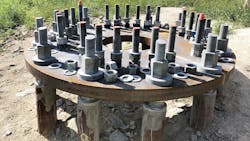
At locations where permanent steel casing was needed (due to sloughing soils and wet conditions), the foundation contractor contacted the design team. They defined the permanent casing installation parameters and accounted for the casings in the design of the foundation. The micropile foundations were used where construction access was problematic. All the installation equipment and material for the micropiles could be flown directly to the structure location by helicopter. The micropile foundations
ranged from a group of six to sixteen micropiles per structure depending on the loading they were required to support and were typically battered at a 2.5° angle. The micropiles were collected at the top with a steel cap plate, which then transferred load to the structure baseplate through 2.25-inch (5.7 cm) anchor bolts.
Helicopter Construction
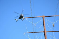
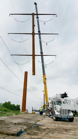
Helicopter construction was used in several different ways throughout the project to place crews, pull ropes, hang insulators, install spacers, and install bird diverters. Additionally, helicopters were used to perform and support structure setting (heavy lift helicopters) where traditional cranes would not have been able to access. They were also used for flying equipment and man-power to limited access remote locations and to install micropile foundations (medium lift).
Structure designs had to account for the helicopter’s lifting capacity limits. The maximum weight that was used in the structure designs was 20,000 pounds (9071.8 kg), meaning that any one section of a structure had to weigh less than this limit.
How the structures were going to be assembled in the field was key to how the structures were designed. The detailing of the structures included “diamond” guides on each section that oriented and allowed the sections of the poles to be set more easily, reducing time and equipment, and increasing safety.
Structure detailing was also incorporated to accommodate the actual linemen that would be charged with the installation work, because the linemen were flown out to the structure site with all the tooling and equipment necessary to complete the installation work.
Linemen needed to get to the top of each section of the pole to bolt the next section to the one below it. To accomplish this, the design team developed removable bail steps that could be inserted into clips that were welded to each pole section that the linemen could stand on while bolting together
the pole sections.
The design of these bail steps was delicate as the steps needed to be large enough for the linemen to stand on safely, but small enough that they were not too heavy to carry with the rest of the tooling needed. The design team also included tie-off clips that were welded to the pole shafts just above the bail step clip
locations that the linemen could tie their fall protection to.
WisDOT Communication Fiber and Railroad Signal Interference
For roughly 100 miles (160.9 km), WisDOT underground fiber optic communication cables ran parallel and underneath the 345 kV transmission line. ATC later learned that this fiber cable was constructed with a metallic armor, which, under certain conditions, could have induced voltage on the metallic armor.
An AC interference analysis was performed and determined that under maximum steady state loading the maximum calculated ground potential rise on the cable could exceed 1400 volts AC, higher than the 50-volt OSHA limit for steady state operating conditions. Mitigation was installed and included: bonding the fiber optic cable armor, adding additional grounding, and grounding the fiber optic cable’s armor to the ground bars at regeneration stations and terminating buildings.
The transmission line is also parallel to the Canadian Pacific Railway (CP) for approximately 40 miles (64.4 km). It is typically a radial distance of 1,000 feet (304.8 m) or more from the transmission line. CP reported to ATC they were experiencing intermittent signaling issues. The team met with CP representatives to understand the signaling system.
The team collected voltage measurements at “Rail to Ground”, “Rail to Rail”, “Across the Insulating Joint (IJ)”, and soil resistivity tests. A Steady Power State AC interference study was completed that evaluated the induction effect against the following parameters:
- Personnel safety – 50 volts maximum between assemble points (rail to ground) including across the IJ
- Equipment operation – 5 volts maximum rail to rail and 2,000 volts for equipment and fault arrestors
Mitigation included the installation of “Dairyland filters” installed at specific IJ locations.
Long-distance transmission lines present numerous and unique challenges for design and construction teams to work on solving. Regulatory and environmental siting requirements may dictate a line routing that isn’t ideal for construction or engineering and design. Projects of this type require significant planning and coordination among many stakeholders and the success of the project typically comes down to the countless efforts of dedicated individuals who are willing to work hard to solve the unique challenges that they are faced with.
About the Author
Griffen Erickson
Griffen Erickson is the Director of Project Operations at Electrical Consultants, Inc. He received his B.S. and M.S. in Civil Engineering from the University of Utah and is a registered professional engineer (PE) and project management professional (PMP). He has over 18 years of experience in the transmission industry.
Michael Bradley
Michael Bradley is a Transmission Line Consultant Engineer at ATC, He has Bachelor of Science in Civil Engineering from University of Wisconsin-Platteville and is a registered professional engineer (PE). He has over 20 years of experience in Transmission Line routing and design. Prior to joining ATC Bradley worked as a consulting engineer in the transportation sector.
Cory Jacobsen
Cory Jacobsen is a Senior Project Manager at Electrical Consultants, Inc. He received his B.S. and M.E. in Civil Engineering from Utah State University and is a registered professional engineer (PE), structural engineer (SE) and project management professional (PMP). He has 15 years of experience in transmission line design.
Jacob Valentine
Jacob Valentine is a Manager of Project Management at ATC. He has a Bachelor of Science in mechanical engineering technology from Purdue University. He has over 18 years of experience in the transmission industry and prior to joining ATC in 2015, Valentine worked in both renewable energy development and process engineering.
