Teamwork Trumps Failure
Florida Power & Light Co. (FPL) is committed to building a stronger and smarter electric grid that provides electricity customers can count on in good weather and in bad. How the utility successfully mitigates outages and restores service following an unanticipated event is one measure of that commitment.
The following incident demonstrates how the FPL mobilized quickly and safely to overcome a challenge to its power delivery system and minimized the impact on its customers.
Immediate Response
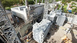
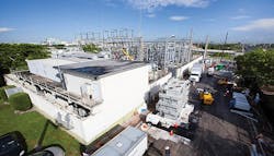
On Sept. 22, 2012, at a substation in downtown Miami, Florida, U.S., a large power transformer failed after experiencing electrical through faults. The substation contained two 93-MVA transformers with 13 feeders in a metal-clad switchgear building feeding both residential load and critical infrastructure, including a medical campus, police stations, fire department headquarters, public transportation and a major arena with nationally televised events.
Replacing the failed transformer posed many engineering and logistical challenges. The immediate concern was the ability to continue serving customers in the area with only one 93-MVA transformer carrying the 68-MVA station’s load. Distribution field switching was performed to reduce loading and the associated risk with the substation. However, limited options in switching prevented the total station load from being picked up. Numerous groups within the transmission, substation and distribution business units mobilized and began planning the transformer’s replacement while activating contingency plans, focusing on three key areas:
- Deploying mobile equipment into the area to reduce customer reliability risk further
- Conducting timely and accurate root-cause-failure analysis for other transformers in the fleet
- Permanently replacing the failed substation transformer.
Initial Hurdles
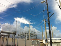
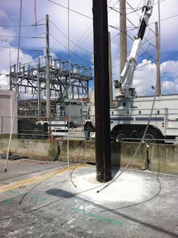
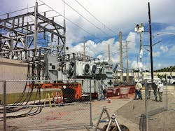
The first technical hurdle the utility had to overcome was prompt deployment and installation of a mobile substation within a highly congested downtown Miami area. The mobile replacement team transported the 40-MVA mobile substation on a 61-ft by 15-ft (18.5-m by 4.5-m) trailer into the congested area. Because of the lack of space within the walled substation and the location of the only overhead transmission line, the team requested permission to block what was normally a busy street to park the mobile substation. An auger was used to bore a hole through the pavement and a 70-ft (21-m) wood pole was set to tap the transmission line.
The quick-thinking solution for the street installation engaged local officials and prompted upfront planning, allowing for seamless delivery with immediate permitting. FPL received a tremendous amount of support from local governments and agencies to facilitate this effort.
A second obstacle was routing the cables from the low side of the mobile substation through the wall and connecting them to the metal-clad bushings on a mezzanine 29 ft (9 m) in the air. To overcome this, the team knocked holes in the wall and routed the cables up a secondary staircase to the switchgear. The mobile substation was energized merely 26 hours after the initial failure occurred.
Root Cause
Because of the logistics at this location, the customary distribution solution for offloading was minimal. To compensate for this setback, the team tied one of the operating buses on the station to the inspection bus on the north substation, which was capable of carrying 14 MVA of load. This was achieved by routing underground residential distribution cables from one yard to the other and temporarily supporting them with wood poles previously set on the sidewalks across the street between both stations.
The situation became more complicated when the on-line transformer diagnostic system signaled imminent failure of the remaining transformer on site. This triggered the start of triage on the in-service transformer while, concurrently, the utility installed the replacement transformer and mobile substation.
Addressing the root cause of the outage was the third area of focus. Detecting root cause failure in a timely manner was imperative because recurrence would jeopardize the second transformer carrying the remaining station load. Aided by the performance and diagnostic center, the responding crews immediately narrowed down the failure to a phase reactor cubicle from one of the feeders on the first transformer.
Crews identified flash marks and damage to the insulators in the phase reactor cubicle. A closer inspection revealed water intrusion and contamination were the causes of the failure. While mitigating the root cause eliminated the possibility of a recurrence endangering the health of the second transformer, the replacement of the first transformer remained a priority.
New Transformer Installation
The installation of the new 55-MVA transformer came with a set of challenges, including different transformer sizing, metal-clad switchgear interconnection and a congested substation environment within a heavily populated area.
Using cranes inside the station was impossible because of the tight quarters; the 364,000-lb (165,108-kg) transformer was slid off its foundation onto a lowboy trailer using rails. Because of the physical difference between the larger 93-MVA transformer and its 55-MVA replacement, the original 3-inch (75-mm) copper tubing design connecting the low-side bushings of the transformer to the metal-clad switchgear bushings required a longer and heavier rigid connection.
Because of the age of the metal-clad bushings and the 6-month lead time, an 8-inch by 8-inch (200-mm by 200-mm) steel beam was custom designed to reduce the weight that would be sustained by the vintage 1972 porcelain bushings. The steel beam, along with insulators, supported and guided two 1000-kcmil flexible copper conductors per phase to replace the original design of the low-side connection.
Electrical connections were improved between the low-side bushings of the new transformer to the metal-clad switchgear bushings. This improvement in construction techniques allowed for a more robust connection with more standard accessibility for maintenance. The 0.75-inch (19-mm) copper tubing connections under the metal-clad switchgear bushings for the station service and metering potential transformers also were redesigned. The weight was reduced by using bare 4/0 copper conductor to clamp off the double 1000-kcmil conductors per phase between the transformer and the switchgear bushings. Additional surge protection to the new transformers was added on the low side, which the previous transformers did not have.
There was not enough room between the transformer and metal-clad building, so low-side surge arresters were never installed on the 93-MVA transformers. On the 55-MVA replacements, surge arresters were mounted on a plate welded to the transformers’ case.
Increased efficiencies between transformer replacements translated into a savings of US$75,000 and helped to improve the second team’s productivity; the second replacement was completed in only four days, which was a five-day improvement. By leveraging this technology, the utility was alerted to an imminent transformer failure and was able to avoid environmental violations, loss of revenue and a reduction in reliability while mitigating exposure to potential safety hazards.
Improved Processes
Despite the initial transformer failure, FPL’s performance and diagnostic center improved the process for dissolved gas analysis data gathered from the utility’s transformer fleet. This data is gathered to help determine the health of the in-service transformer fleet. This complex use of technology directly impacted the decision-making process to proactively replace the second transformer, which was displaying signs of a violent failure.
The main project improvements resulted in better service reliability for customers. FPL improved the transportation response time by implementing a pre-rollout meeting, completing a road-ready inspection before drivers arrived and having a standby crew ready to assist with potential automotive issues. Previously, these items were managed on a reactive basis.
This project demonstrates how a diversified team from engineering, transmission, substation, construction, field operations and technical services overcame a set of difficult circumstances by leveraging technology and innovation while maintaining a commitment to excellence and safety.
Allen Khalili ([email protected]) is area transmission/substation and protection and control manager at Florida Power & Light. He has worked at FPL for the past 33 years in the transmission/substation and protection and control area. He holds a BSEE degree from the University of Miami.
Jose Alvarez Garcell ([email protected]) is a substation engineer at Florida Power & Light. He has been with the substation group for more than three years. Garcell holds a BSEE degree from Florida International University.
Jow Ortiz is transformer team manager at NextEra Energy, the Florida Power & Light holding company. He has been with NextEra Energy for 16 years and is responsible for the procurement and maintenance of transformers, arresters and regulators at FPL and NextEra. Ortiz holds a BSEE degree in applied physics from the University of Miami.
