Smart Planning Keeps the Lights on in Paradise
The long chain of islands known as the Florida Keys is serviced by two separate electric utilities: Florida Keys Electric Cooperative in the Upper Keys and Keys Energy Services in Key West, Florida, U.S. While the geography and natural beauty of the Keys elicit praise and delight from those who visit, that same geography can create significant challenges for the two electric utilities, which need to not only keep the lights on but continuously upgrade and improve the existing T&D systems.
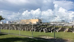
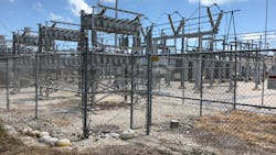
Both Florida Keys Electric Cooperative (FKEC) and Keys Energy Services (KEYS) faced such challenges over the last two years, as the utilities sought to replace and upgrade all existing protection and control at FKEC’s Marathon substation, located midway between Key Largo and Key West. This substation represents a critical junction point between the eastern and western Florida Keys, as well as the interconnection point between the service territories of both utilities.
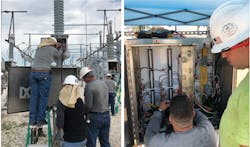
FKEC tapped Powerserve Technologies Inc. (PSTI), a contractor that specializes in protection and control work in energized substations, to complete the project. It had to be planned and executed carefully, as the Marathon substation is fed from the northeast by a single transmission line and serves as the source for a single transmission line that is the only feed to the city of Key West. The configuration of the 128-kV bus is such that only one-half of the bus and one transformer had to be isolated to change the CCVT junction box. The line outages had to occur during off-peak hours overnight for two nights; minimizing to the fullest extent possible outages east and west of Marathon as far as Key West.
Project Scope
Marathon’s substation consists of the following electrical facilities:
- A single 138-kV ring bus with three SF6 circuit breakers
- Two 138-kV transmission lines
- Two 28-MVA, 138/25-kV power transformers for serving distribution load
- Three 138-kV capacitor banks connected by three SF6 circuit breakers
- Five 25-kV feeder breakers
- Three 138-kV circuit switchers.
In 2017, PSTI was the successful bidder for this project, which included the removal or modification of 10 existing relay panels from the old relay room in the control enclosure. The company was called on to provide, install and commission all the ancillary systems, the alternating-current (AC) load center, the complete direct-current (DC) system, the enclosure lighting and the electrical system. PSTI also designed, fabricated, installed and tested 11 new panels in a new control enclosure. Additionally, it provided operational commissioning of all protective, control, and supervisory control and data acquisition (SCADA) systems to prove correct operation to the existing substation equipment with only minimal interruption to the normal operation of the Marathon substation.
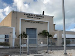
The new control enclosure was once an office building that had been demolished; only the exterior walls and roof remained. New concrete block walls were added to create a separate battery room. A new DC standby system was designed and installed to provide power to the relays and substation equipment. A new cable tray system was designed and installed. New lighting and receptacles also were installed.
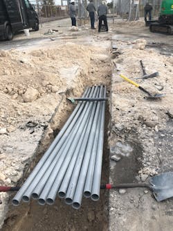
The new control enclosure required a completely new raceway system. Therefore, a new cable trench was installed to strategically shorten conduit runs to the existing equipment. Conduits were installed between the new cable trench and existing equipment. PSTI performed exploratory hand digging throughout the substation yard to determine where new cable trench could be located. This was difficult because of numerous shallow existing conduits.
To keep existing substation protection and control systems in operation, the existing conduits could not be disturbed. A new cable trench was ordered to fit the routing that had been selected. Because of preexisting site conditions, the trench today varies in width and depth to accommodate the new control wiring.
Working closely with FKEC during the design phase, PSTI designed new relay panels and new control logic, all the while keeping the existing generation protection interconnections to the 25-kV system. The new relay panels are lighter, simpler, and easier to access than the old relay panels. The new control logic was designed to match FKEC’s current relay philosophy. The work also included designing replacement transformer load-tap changer controllers and position indicators.
Minimizing Outages
Early in the design process, the complexity of the project began to surface. Issues regarding clearances, existing protection and control systems, and coordinating the ongoing work among and between the two Keys utilities soon emerged as the most challenging aspects.
PSTI was approached by FKEC to try to determine the minimum outage time in which the work could be completed. This was a significant challenge. The reason for the request was because moving the protection could not be done in a single night. This quickly became the critical path, as clearances longer than a single night could not be granted. After conversations with FKEC regarding its minimum protective relay elements, PSTI created a plan to move the protection of both line terminals with only two short night clearances to install new junction boxes for the line protection potentials.
The plan was to operate the station with protection and control system operation split between both the old and new control enclosures. For example, the 138-kV bus differential protection and local breaker control were moved to the new control enclosure while line protection was left in the old control enclosure. This plan was complicated by the configuration of the existing protection and control system that had been in place for many years. Over the intervening years, the system had undergone numerous modifications and upgrades as a result of partial modernization, protection philosophy changes and even changes in key FKEC personnel. All these changes led to relays performing similar protection functions being located on disparate panels.
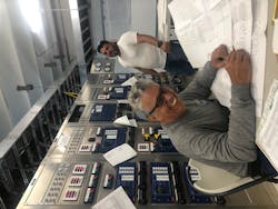
The only way to execute the plan was to move the line protection of both lines one breaker at a time. This meant each line had to be protected from the old existing panel for a time period, with currents passing through the new relay in the new control enclosure. Prior to performing any work, PSTI spent considerable time verifying as much of the existing wiring as possible. Even more time was spent determining specific step-by-step wiring changes in a sequence that would minimize the risk of unintended operations. One mistake would put the city of Key West in the dark, shutting down its sole source line.
The plan was written in modules to enable some flexibility for accommodating station load. Contingencies were incorporated so modules could be executed in any order with minimal temporary circuits. This resulted in the following sequence of protection migration:
- 138-kV line potentials were moved.
- 25-kV bus differential protection was moved.
- 138-kV bus differential protection was moved.
- 25-kV potentials were moved.
- 25-kV feeders were moved.
- 138-kV ring bus breaker failure protection and line protection was moved.
- Three 138-kV capacitor banks protection were moved.
- Once peak load subsided, the first power transformer, primary-side circuit switcher and secondary-side circuit breaker protection was moved.
- Second power transformer, circuit switcher and breaker protection was moved.
Once all protection was moved into the new control enclosure, the existing relay panels were completely isolated to enable removal from the existing control enclosure. All this was completed without a single inadvertent operation.
Challenges and Breakthroughs
The most important results of this two-year project were that it was completed on time, within budget and without a single safety incident. While the outcome was positive, some challenges had to be overcome along the way:
- There were two nights in February 2019 when PSTI and FKEC had to work the graveyard shift, from 9 p.m. to 6 a.m. During these two nights, KEYS was disconnected from the Eastern Interconnect, the Florida Reliability Coordinating Council (FRCC) region. On one of those nights, Marathon also operated in an island condition. Therefore, two islands (the Marathon substation and KEYS) were operating in the FRCC region.
- There were two nights in August 2019 when PSTI had to work during the evening hours to move the capacitors to the new control enclosure, as the capacitors were needed during the day to maintain the voltages.
With the challenges also came several technological breakthroughs during the project:
- The automating reclosing scheme of the 138-kV Marathon-Big Pine line provides a reliability benefit to the 30,000-plus customers served by KEYS. Before the new control enclosure, it took five minutes to interconnect KEYS to FKEC. Now it is automatic and takes only seconds.
- Marathon-Big Pine line is protected by a primary high-speed differential scheme (SEL-411L) and a secondary high-speed distance relay (SEL-421) from Schweitzer Engineering Laboratories Inc. (SEL). Now, the primary SEL-411L also has as backup a high-speed distance permissive overreaching transfer tip (POTT) scheme as well, which is unique. The SEL-411L also has traveling wave capability, used to locate where a fault occurs.
- Both of the distribution transformers now have new Beckwith Electric Co. Inc. controls with fiber connections to the real-time automation controller in the new control enclosure.
- All 10 new control panels have state-of-the-art equipment, and all the facilities now are operated by the same relays protecting the facilities.
- There are no longer any mechanical, tagging or auxiliary relays in the new control enclosure.
- The old control enclosure provided FKEC an inventory equivalent to more than US$30,000 in relays that can be used throughout the utility’s substations.
PSTI’s transition plan included more than 3400 lines of instructions. It was this level of detail that resulted in a smooth, well-executed transition to the new protection and control. FKEC personnel have been trained in testing, programming and troubleshooting to ensure success going forward.
Acknowledgments
Rasiel Martinez, Powerserve Technologies Inc.
For more information:
Beckwith | https://becwithelectric.com
PSTI | https://powerservetech.com
SEL | https://selinc.com
FKEC’s Reasons for Change
Florida Keys Electric Cooperative (FKEC) decided to replace and upgrade all its existing protection and control for these main reasons:
- Improve the T&D reliability at its Marathon substation
- Separate the monitoring, control, protection and control of the transmission from the generation
- Move the transmission away from the water about 600 ft (183 m)
- Improve the 138-kV Marathon-Big Pine transmission line reclosing scheme.
The utility faced a few challenges with this project:
- Florida Keys are radially connected to the mainland from the north
- Had to move the monitoring, control and protection of facilities while they were in service during the summer peak load
- Had to maintain Keys Energy Services’ interconnection while transitioning to the new control enclosure
(Source: Alberto Gonzalez Novoa, Protection and Control Engineer, FKEC.)
About the Author
Alberto Gonzalez-Novoa
Alberto Gonzalez-Novoa is a relay engineer for the Florida Keys Electric Cooperative, Inc. He holds a BSEE from Florida Institute of Technology, MSEE from Georgia Institute of Technology, and an MBA from Florida International University. He is also a member of IEEE.
Mike Miller
Mike Miller, P.E., works for Powerserve Technologies, Inc with 20 years of experience in designing and implementing protection and control schemes. He has a BSEE from the University of Central Florida, is a professional engineer in the State of Florida, and a member of IEEE.
