Point-to-Point Digital Secondary System Design for a Transmission Substation: Part 2
In Part 1 we described a point‑to‑point digital secondary system (P2P DSS) design for an existing 100 kV transmission substation at Duke Energy, using point-to-point (P2P) intelligent electronic device (IED) and merging units (MU) available from an IED manufacturer, the P2P DSS is designed for the entire substation. In Part 2 we compare the two designs analytically by using device count, protection scheme unavailability, and protection system operation speed as criteria, and Duke Energy’s future plans.
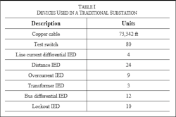
Device CountTable I below, lists various devices used in the traditional substation. In a traditional substation, copper cables connect CTs and PTs secondary to IEDs. Similarly, copper cables are used for connection between breakers and IEDs for control. The total copper cable length of 73,342 ft is calculated using 4c12 cable type for CTs and PTs and 3c8:9c12 cable type for control.
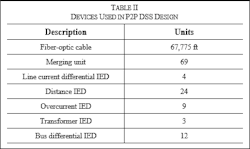
A tabulated list of devices used in the P2P DSS design is shown in Table II. The P2P DSS is designed to maintain the existing protection philosophy and operation methodology. As a result, the number of IEDs remains the same between the two designs. A total fiber-optic cable length of 67,775 ft is calculated by assuming a cable with 2 fibers. The total length decreases significantly if fiber-optic cables with 4 or 8 fibers are used. A total of 69 MUs and 52 IEDs are used in the P2P DSS design. As discussed in the Part 1, 10 MUs alone are used for distributing the Red and Yellow Bus voltages to 38 IEDs. Adding 69 MUs will require the station dc power system capacity to double. Finally, test switches and lockout IEDs are no longer needed in P2P DSS.
The well-known fault tree analysis technique was used to compare the two designs’ relative unavailability of protection schemes. A fault tree consists of a top event, the failure of interest, and basic events related to the top event and is typically expressed with a logic gate. Unavailability is the fraction of time when a device cannot function. It is unitless.
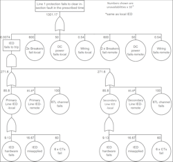
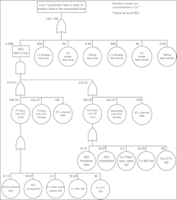
The fault tree analysis is carried out on Line 1 protection scheme for both the traditional system and P2P DSS design. The top event for the analysis is Line 1 protection fails to clear the in-section fault in the prescribed time. For this top event, we assumed that the remote substation design is identical to the local substation. Fig 1 shows the fault tree for the top event for the traditional substation. This fault tree is constructed using the traditional protection system design shown in Part 1. This failure occurs if breakers, CTs, PTs, dc power system, wiring, 87L channel, or IEDs from either local or remote substation fail. Using redundant line current differential IEDs and CTs lowers the unavailability to 0.0074e-6 from 271.6e-6 for a single-line current differential scheme. Note that the substation under study has only one dc power source for both primary and secondary systems. The dc power system includes batteries, battery chargers, and dc power distribution.
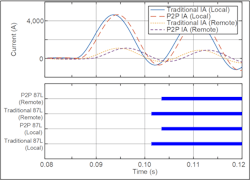
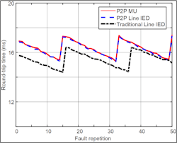
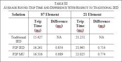
Fast protection speed is one of the requirements for transmission substations at Duke Energy. Fast protection system operation speed results in faster fault-clearing time. When faults are cleared quickly, it enhances personnel safety, limits equipment wear and equipment damage, and improves the power quality. Similarly, transient stability is improved, and the power transfer can be increased when faults are cleared faster than the critical clearing time. In this subsection, we compare traditional IEDs’ protection system operation speed with that of P2P DSS IEDs.
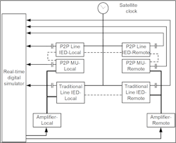
The test setup used to compare the two solutions’ protection system operation speed is illustrated in Fig 3. A simple two‑source power system connected by a transmission line is modeled in a real-time digital simulator. Both IED pairs are configured with the same protection settings to protect a line. P2P Line IEDs have one binary output board, allowing the IEDs to send control signals to breakers or other IEDs. High-speed output contacts from traditional IEDs, P2P MUs, and P2P IEDs are connected to the simulator to send the trip signal.
Lessons Learned
Many lessons have been learned from this case study. With the design requiring full redundancy in all devices and relays, the number of MUs and IEDs required was quite significant (52 IEDs, 69 MUs). This issue alone would result in the need for a much larger substation battery. The full redundancy requirement with the P2P provided a highly reliable design with virtually no impact on protection reliability. Limitations were noted with the number of ports on the MUs when applied to the substation design used in this study. This substation also has many breakers (and CTs) per bus section and one set of bus PTs tied to many relays.
Initial plans are to start with lab testing of the P2P technologies. This testing will include formulating plans for how all components would be tested and commissioned in the field. Initial testing in the laboratory would allow setting engineers the opportunity to convert existing setting templates to what would be required for the P2P technology. The next steps would include introducing the new technology to field resources to determine the testing required and how commissioning would occur in the actual substation.
After the lab testing and development work with field technicians is completed, plans would include selecting a predeployment location on the system. Initially, a transmission line terminal would be selected, allowing all the traditional line protective relaying to be replaced with a new standard protection package and a third relay utilizing the new P2P technology. No tripping would be allowed from the new P2P relay, but this would allow the full testing and commissioning process to occur in a substation. Caution should be utilized in moving any new technology from the lab to the real world. Any system faults that occurred within the protected line would allow for the full comparison of relay speed in tripping. Any faults outside of the protected line would provide confidence in the security of the new technology. There is no better way to build confidence and a working knowledge of a P2P protection package other than by evaluating how it operates and performs in a real application.
Future Plans
Duke Energy views the use of P2P DSS technology as an opportunity to reduce the amount of copper utilized in traditional substation protection designs. To learn more about P2P technology, a detailed P2P DSS design for Duke Energy’s existing 100 kV transmission substation was carried out as a collaborative case study. The P2P MU and the protection IEDs used for the case study have four and eight communication ports, respectively. This port limitation poses a unique challenge when implementing bus differential protection for 10 breakers. Similarly, supplying bus voltages to 18 IEDs requires multiple MUs connected to the same PT source. Following the design, the P2P DSS was compared against traditional design using total device count, protection scheme unavailability, and protection system operation speed as criteria. It was observed that the P2P DSS design requires multiple MUs. On the other hand, protection scheme unavailability and protection system operation speed are found to be very close between the two designs.
Duke Energy is planning to use the technical data from this case study to evaluate P2P technology. In addition, the plan is to start lab testing on P2P MU and P2P relays. Following successful lab testing, the company plans to pursue the predeployment of P2P technology in a transmission line application.
Stephen B. Ladd received his BSEE from Grove City College in 1986, MSEE from Georgia Tech in 1987, and MBA from Queens University of Charlotte in 2003. He has been a member of IEEE for 37 years and a member of IEEE-PES since 1987. He is a registered Professional Engineer in the state of North Carolina and has worked at Duke Power, Duke Engineering & Services, and Duke Energy Corporation since 1987. Ladd has held engineering positions in Substation Apparatus, Protection & Control, and Asset Management. He is currently a Principal Engineer in the Transmission System Standards group.Arun Shrestha received his BSEE from the Institute of Engineering, Tribhuvan University, Nepal, in 2005, and his MS and PhD in electrical engineering from the University of North Carolina at Charlotte in 2009 and 2016, respectively. He joined Schweitzer Engineering Laboratories, Inc. (SEL) in 2011 as an associate power engineer in research and development. He is presently working as a senior engineer. His research areas of interest include power system protection and control design, real-time power system modeling and simulation, wide-area protection and control, power system stability, and digital substations. He is a senior member of IEEE and is a registered Professional Engineer. He is a member of IEEE PSRC and a U.S. representative of IEC 61850 TC 57 WG 10.
About the Author
Stephen B. Ladd
Stephen B. Ladd received his BSEE from Grove City College in 1986, MSEE from Georgia Tech in 1987, and MBA from Queens University of Charlotte in 2003. He has been a member of IEEE for 37 years and a member of IEEE-PES since 1987. He is a registered Professional Engineer in the state of North Carolina and has worked at Duke Power, Duke Engineering & Services, and Duke Energy Corporation since 1987. Mr. Ladd has held engineering positions in Substation Apparatus, Protection & Control, and Asset Management. He is currently a Principal Engineer in the Transmission System Standards group.
Arun Shrestha
Arun Shrestha received his BSEE from the Institute of Engineering, Tribhuvan University, Nepal, in 2005, and his MS and PhD in electrical engineering from the University of North Carolina at Charlotte in 2009 and 2016, respectively. He joined Schweitzer Engineering Laboratories, Inc. (SEL) in 2011 as an associate power engineer in research and development. He is presently working as a senior engineer. His research areas of interest include power system protection and control design, real-time power system modeling and simulation, wide-area protection and control, power system stability, and digital substations. He is a senior member of IEEE and is a registered Professional Engineer. He is a member of IEEE PSRC and a U.S. representative of IEC 61850 TC 57 WG 10.
