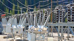
The use of air-break disconnect switches to interrupt the capacitive currents associated with open‑ended bus runs and short lines is common practice. In most cases, the current magnitude is no more than 2 A but may be even higher requiring the use of auxiliary interrupting devices such as whips. The switching duty, often performed with manually operated switches, is not an exact science and practices are often based on trial-and-error.
One particular phenomenon experienced by practically all utilities is a wide variation in the interruption process for the same load current. In one substation the interruption is fast with only a short period of arcing; in another substation with the same switch type and exactly the same load current, the interruption is a noisy prolonged arcing event. An investigation, initiated first at BC Hydro, at the Eindhoven University of Technology and KEMA (now DNV‑GL KEMA Laboratories) showed that the difference in performance for the same load current was related to the ratio of the capacitances on either side of the switch. This is explained in the following after first discussing phenomena associated with low current arcs in air.
Low Current Arcs in Air
Current interruption using air-break disconnect switches is a self-extinguishing event. At contact parting an arc is drawn and extinction is dependent on the switching case, i.e. transformer magnetizing current, capacitive current or loop current and the nature of the arc [1]. For successful switching, the current should of course be interrupted while the moving contact is still in motion.
For capacitive currents, usually not exceeding 5 A in practice, the nature of the arc is dependent on the magnitude of the current [2, 3]. For currents below 1 A, the arc will not exhibit any thermal properties. This means that the arc will not rise due to convection and each restrike will follow a new path. Interruption is essentially a dielectric event dependent on achieving an open gap capable of withstanding the recovery voltage. Above 1 A, the arc will exhibit thermal properties and the arc will rise and grow in length due to convection. Restrikes will now follow the previous arc path however convoluted it may be and ultimate interruption is now more complex involving arc power as discussed below.
Capacitive Current Switching
The circuit for capacitive current switching is shown in Figure 1. In general, the switching event has been viewed as solely involving interactions between the system as represented by VS and LS and the load circuit . At current interruption is charged to the peak value of VL and the disconnect switch recovery voltage peak is thus 2 pu after one half-cycle. Restriking was in turn taken as being solely an interaction between the system and CL. However, this scenario does not explain the prolonged arcing phenomenon noted above. A test run at the KEMA Laboratories at Arnhem in The Netherlands provided the explanation showing the presence of an initial local interaction involving CS and CL.
Referring to Figure 2, restriking actually takes place in two stages. In the first stage, the initial breakdown spark between the contacts results in an exchange of charge between CS and CL to equalize the voltage, designated as the equalization voltage VE, on both capacitors. VE is not equal to the source voltage and, in the second stage of the restrike, the voltage at both capacitors recovers to the source voltage by way of a transient oscillation.
So now the question is: why does prolonged arcing sometimes occur for fixed values of CL and the load current? The answer lies in the relative values of CS and CL. If CS > CL, the equalization voltage VE will be close to the source voltage and the subsequent transient oscillation will be small and of low energy and having minimal effect on the arc duration (Figure 3 upper trace). However, if , the opposite is true. will now be close to the load‑side DC voltage and the transient oscillation will be large injecting significant energy into the arc thereby forcing a prolonged arc duration (Figure 3 lower trace). The effect of the ratio CS ⁄ CL on arc duration is shown in Figure 3. In addition, the magnitude of the switching overvoltages will be higher for CS ⁄ CL < 1 as shown in Figure 4.
Capacitive Current Switching Type Testing
Type testing of disconnect switch capacitive current interrupting capability is covered in IEC TR 62271‑305 [4]. The document as it stands proposes testing at a CS ⁄ CL ratio of 0.1. This is viewed as unrealistic with respect to actual applications and the upcoming revision will change this to one of agreement between the manufacturer and the user reflecting the actual application values for CS and CL.
References
- D.F. Peelo, R.P.P. Smeets, J.H. Sawada, B.R. Sunga, J.G. Krone, L. van der Sluis and S. Kuivenhoven, “Current Interruption with High Voltage Air-Break Disconnectors,” Paper No. A3‑301, Cigre 2004 Session.
- D.F. Peelo, R.P.P. Smeets, S. Kuivenhoven and J.G. Krone, “Capacitive Current Interruption in Atmospheric Air,” Paper No. 106, Cigre SCA3 and B3 Joint Colloquium, Tokyo 2005.
- Y. Chai, P.A.A.F. Wouters, R.T.W.J. van Hoppe, R.P.P. Smeets and D.F. Peelo, “Capacitive Current Interruption with Air-Break High Voltage Disconnectors,” IEEE Transactions on Power Delivery, Vol, 25, No. 2, April 2010.
- IEC/TR 62271-305: High-voltage switchgear and controlgear – Part 305: Capacitive current switching capability of air-insulated disconnectors for rated voltages above 52 kV.


