Impact of a Car Crash on a Steel Transmission Pole
Given that roadside power utility poles are very common in the United States, they are easily hit by errant vehicles. The extent and pattern of damage to the pole and the vehicle when a crash occurs depend on various factors such as vehicle size, vehicle speed, pole size and pole location.
Tests to determine the outcomes of a vehicle crashing into a fixed object, such as a pole, have been performed, but not for transmission-class steel poles. In one test, pendulum impact test conditions were used, whereby an 1800 lb (820 kg) pendulum mass with a crushable honeycomb nose crashed into a composite pole at 20 mph (32 kmph)[1]. The Federal Outdoor Impact Laboratory (FOIL) at the National Crash Analysis Center (NCAC) has a propulsion system that can be used to accelerate a 4400 lb (2000 kg) vehicle to speeds of up to 75 mph (120 kmph) and a 17600 lb (8000 kg) vehicle to speeds of up to 50 mph (80 kmph). The Insurance Institute for Highway Safety (IIHS) has embedded in the ground a propulsion system that can propel a test vehicle to the desired speed. Once accelerated to the test speed, the test vehicle is released by the propulsion system 25 cm in front of the point of impact (a barrier)[2]. The unleashed test vehicle strikes the barrier such that a collision scene is simulated.
To study full-scale crashes, researchers at FOIL performed several crash tests at Mclean, Virginia[3] in 1996 using test vehicles ranging from a surrogate bogie vehicle to a full-size Chevrolet 2500 pickup truck. The purpose of these tests was to verify that poles built with a new rigid design were operationally and structurally sound. The test speeds varied from 21.7 mph (35 kmph) to 29.8 mph (48 kmph). In addition, three lateral pole crash tests were performed in New Jersey in 2008[4] by the New Jersey Association of Accident Reconstructionists (NJAAR). The vehicles were set up on a dolly system and pulled sideways into class-three wooden utility poles. The cable used to pull the test cars was released, after which the crash immediately occurred.
In the present study, a full-scale crash test was performed in order to closely examine the results of a vehicle crashing into a transmission-class pole, which means a pole with a voltage of at least 69 kV. The test was performed on an 80-ft H4-class steel pole and a popular passenger vehicle traveling at 36 mph. A detailed account of both the test setup and results is presented in the following sections.
COLLISION TEST SETUP
Test Vehicles
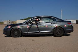
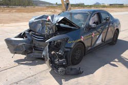
The most frequently registered passenger vehicle (Figure 1) from 2010 to 2014 in the service territory of Pepco Holdings (Delaware, Maryland, New Jersey and Washington, DC) was used in the test.
The vehicle was ballasted to the test weight. A tow and brake abort system was installed. Two triaxial accelerometer sets were mounted onto the vehicle. A fully charged gel cell battery was placed in the trunk to power the airbag system during the crash. High-speed cameras were installed on the sides of the car and front window openings to capture the motion of the vehicle occupants, the anthropomorphic test devices (ATDs) also referred to as crash test dummies. The total weight of the vehicle was 3663 lb (1662 kg).
Occupants
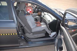
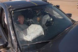
Two ATDs (Figure 2) were positioned inside the test vehicle to simulate the driver and a passenger. The driver ATD was a Hybrid III 50th-percentile male and the passenger ATD was a Hybrid III 5th-percentile female.
Transmission Steel Pole
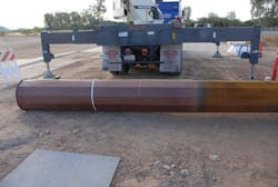
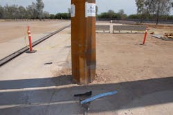
A H4-class steel pole (Figure 3) made of ASTM A871 self-weathering steel was used in the test. The pole had a yield strength of 65 ksi (448 MPa) with a Charpy V-Notch Impact Value of 15 ft-lb (20.3 joules) at -20°F/-29°C (Heat Lot Tested).
The base diameter of the bearing plate was 24.25 inch (616 mm) and the setup also included a taper of 0.188645 in/ft (15.72 mm/m) for the pole. The pole consisted of two sections assembled by press-fitting one on top of the other through a slip joint. Each of the two pole sections was a regular dodecagon (12-sided polygon). The wall of each pole section was 0.1875-inch (4.763-mm) thick. The assembled pole weighed 3006 lb (1363 kg). The designed groundline moment was 382 kip-ft (518 KN-m).
Foundation
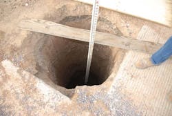
The pole was directly embedded in a drilled hole in the ground to a depth of 14 ft (Figure 4), which is the sum of 10% of the pole length and an additional 6 ft. After the pole had been inserted into the drilled hole, the excavated soil was refilled back to the annulus space between the pole and the drilled hole.
Finally, a 500-lb weight bag was hung at the top of the pole to simulate the conductor weight typically supported by this kind of pole.
CRASH TEST
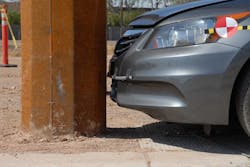
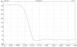
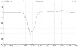
The crash zone of the vehicle was about 1 ft above the ground (Figure 5). The test vehicle was accelerated to the designed speed of 36 mph before crashing into the steel pole. The entire crash occurred within a very short timeframe (Figure 6). Within 0.12 seconds, the vehicle velocity had changed from 36 mph to 7 mph in the opposite direction. The acceleration time history, showing the peak of acceleration at around 41 g, is represented in Figure 7.
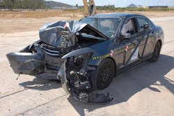
Multiple snapshots of the crash scene are shown in Figure 8. High-speed cameras were used in several locations to capture the movements of the vehicle and the test ATDs at various points in the crash event. Top and side views of the crash outcomes are shown in Figure 9. The front bumper of the vehicle is wrapped around the pole and the front hood is shown to be buckled. The pole also shows significant damage from the crash event. At the exact moment of the impact, the front and side airbags were deployed to protect the driver and the passenger.
CRASH TEST RESULTS SUMMARY
The crash caused a 3-inch deep dent in the pole with the several flats of the pole buckled inward (Figure 10) and permanent damage to the front of the vehicle (Figure 11). Based on the recorded data from the sensors on the ATDS, the neck injury index was below the published Injury Assessment Reference Values (IARVs), which represents a low risk of serious injury. Engineers and researchers can draw on these results to further their understanding of the impact of a crash and take corresponding measures in their engineering designs.
The purpose of this article is to provide information pertaining to the results of a vehicle crashing into a roadside steel pole. Because of various factors such as cost and maintenance issues, most steel poles at the roadside are not protected from road traffic.
A full-scale crash test for a H4-class steel pole was performed using a popular passenger vehicle traveling at 36 mph. The pole was embedded in the ground at a depth of 14 feet. The pole remained upright after the impact but the wall of the pole near the groundline level sustained a dent 3 inches deep. The airbags at the front and sides of the vehicle all deployed to buffer the impact during the crash and injuries to the necks of the ATDs were determined to be minor as interpreted in reference to the published IARVs.
ACKNOWLEDGEMENTS
The author would like to acknowledge and express gratitude to Richard Steeg, former transmission engineering manager at Pepco Holdings, who sponsored the test described in this study, and to Drew Pizzo, senior project construction manager at Pepco Holdings, who observed the test.
REFERENCES
- Richard Foedinger et al., Development of an Energy Absorbing Composite Utility Pole, Transportation Research Board, 2002.
- Side Impact Crashworthiness Evaluation Crash Test Protocol (Version VII), Insurance Institute for Highway Safety, May 2014.
- Christopher M. Brown, Dynamic Evaluation of the New FOIL Instrumented Rigid Pole: FOIL Test Numbers 96F008 through 96F015, 1998, USDOT Report NO FHWA-RD-99-026.
- Andrew Rich, Joseph Cofone, Michelle Schramm, and Daniel Vomhof III, 2008 Joint Conference Lateral Pole Crash Test Results, http://www.4n6xprt.com/2008_Joint_Conference_Lateral_Pole_Crash_Test_Results_with_Supplement_for_Momentum.pdf, Accessed June 21, 2018.
About the Author
Haijian Shi
Haijian Shi, PhD, P.E., P.M.P., works on transmission reinforcement at Pepco Holdings, an Exelon company.
