De-Energization Is A New Tool to Fight Wildfires
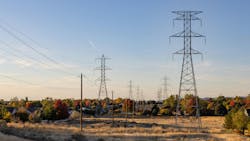
Americans are no strangers to wildfire smoke. Between 2012 and 2021, the U.S. experienced, on average, more than 60,000 wildfires per year. Statistics show most wildfires in the U.S. are caused by humans, with sources including vehicles, cigarettes, campfires and prescribed burning. Malfunctions with electrical distribution equipment, such as broken power lines and conductors, also can spark a fire.
To mitigate the wildfire risk associated with overhead conductors, the electric power industry has several tools at its disposal:
- Vegetation management comprehensively reduces risk by minimizing available fuel to burn.
- High-impedance fault- and arc-detection algorithms in protective relays increase equipment sensitivity, making a trip and de-energization before ignition more likely even when fault current is low.
- Operational policies, such as disabling reclosing in high-risk conditions, reduce the total energy delivered to fuel but reduce reliability.
- Undergrounding of conductors drives the risk of ignition to near zero, but at significant time and expense as well as changes in charging current requirements.
In addition to these options for mitigation, a new method exists to mitigate risk from downed conductors that is being made more impactful by the proliferation of high-speed communication systems. It can be implemented using equipment from multiple suppliers and is being deployed by utilities throughout the western U.S.
Cutting Power
A wildfire is an equation: Fuel + Oxygen + Heat = Fire.
In the case of conductor contact with the ground, the fuel and oxygen are provided by nature. The heat is provided by an electrical arc. The most effective way to change the right side of the equation is to remove a term from the left side. Vegetation management can drive the fuel toward zero, but not completely. Fortunately, it is possible to remove heat: Do not wait for the fault or the arc, but instead look for the broken conductor itself and de-energize it before it can hit the ground.
This concept has been in service in western U.S. utilities since 2015. The challenge of incorporating modern protective relays, substation or edge automation controllers with high-speed communication systems is scalability.
More Data, More Devices
With broken conductors, the clock starts ticking the moment the line breaks. The total time available to measure, detect and de-energize a conductor is a function of altitude above ground level; on average, it is approximately 1.4 seconds. To use this new protection technology, there must be protective devices nearby. This not only minimizes customer minutes of interruption (CMI) by de-energizing as little line as possible, but it also improves system sensitivity by providing more data in close event proximity.
Synchronized phasor measurements from a phasor measurement unit (PMU) associated with breaker, recloser and switch controls are streamed continuously over a high-speed communication network to an automation controller, located either in a substation or in a pole-mounted enclosure. Historically, these solutions have required fiber or point-to-point radio but now are being commissioned successfully on private LTE networks.
The measurement transmission time due to radio latency is approximately 50 milliseconds. Data time alignment and connectivity model-based analysis can be accomplished in 200 milliseconds. Trip signal transmission to the nearest protective devices takes another 50 milliseconds. Protective relay processing and primary equipment operation time take 80 milliseconds or maybe a few more. Total time to operate is less than 500 milliseconds. This leaves a little more than 1 second for variability in communication system latency or algorithmic security; therefore, falling conductor protection is demonstrably possible over several different communication mediums.
Detection Methods
Several changes in measured quantities are observed when a conductor breaks, and all are useful in detecting the event:
- Measuring the rate of change of per-phase voltage (dV/dt) — A broken conductor results in the downline voltage falling toward zero, resulting in the magnitude of dV/dt increasing sharply. This occurrence can be corroborated by also observing the zero-sequence voltage rate of change (dV0/dt).
- Monitoring the zero- and negative-sequence voltage magnitudes — When comparing these magnitudes from PMUs on either side of the break location, the downline PMU indicates a sustained rise in V0 or V2 magnitudes.
- Monitoring the zero- and negative-sequence angles — When these angles are compared across several PMUs, they should remain relatively aligned. When a conductor breaks, the angles reported by PMUs between the source and the break remain aligned, but the angles reported by PMUs downline of the break deviate from those on the source side of the break.
Because synchronized phasor measurements (using IEEE C37.118) are used, care must be taken to ensure all quantities are correctly time-aligned to prevent newer messages from one PMU being inadvertently compared to older messages from another PMU. This could cause a false broken conductor detection.
The numbers streaming to the automation controller are measured quantities and, therefore, dependent on the proper functionality of the measurement equipment and circuitry. Broken conductor detection algorithms should account for the possibility potential transformers (PTs) measuring voltage may go bad. They should also account for blown fuses, connectivity model errors, operation of the feeder circuit breaker, presence of a fault and other occurrences that could result in misoperation.
Falling Conductor Protection
Like many technologies, falling conductor protection has experienced a lag between when it was proven (nearly 10 years ago) and when it became scalable. This is often due to a missing critical piece or a design that is not simple enough. For years, the missing piece was reliable high-speed communications capable of streaming PMU data and delivering trip signals before the conductor hits the ground.
Now that those communications are more prevalent, falling conductor protection technology is a fast, safe, reliable and economical solution for utilities to help prevent wildfires caused by downed conductors. And, it is technology that will only improve with time, as engineers and computer scientists continue to prioritize simplicity, scalability and speed of deployment in their designs.
Bryan Fazzari, Schweitzer Engineering Laboratories Inc.
About the Author
Bryan Fazzari
Bryan Fazzari, Schweitzer Engineering Laboratories Inc.

