Utilities traditionally have understood faults are an inescapable part of the distribution system. Overhead faults can stem from equipment failures and contact with objects. Faults can lead to phase-to-phase arcing, phase-to-ground arcing and downed conductor when the fault current surpasses the conductor’s short-circuit duty limit. Resulting arcs and energized downed conductors are potential ignition sources that can lead to wildfires.
Historically, Southern California Edison (SCE) has followed the standard utility practice of using bare overhead wire and relying on protection systems to detect and isolate faults. When a fault causes a surge in current, protective relays trigger the circuit to be deenergized. During the fault isolation process the circuit may be reenergized, which can cause repeated fault conditions until the protective relay locks out the circuit. While this protection scheme is considered reasonable by industry standards, it is reactive, not preventive. Consequently, despite the shortened duration of the fault, the arcing caused by the fault may create an ignition source.
As a result of climate change, drought and a significant buildup in fuel, the fire season in California starts earlier and lasts longer. The fires themselves now are larger and more intense. Since October 2017, California has experienced 12 out of the 20 most destructive fires in its history. In 2020 alone, nearly 9000 fires burned more than 4 million acres (1.6 million hectares) as of the end of October, at the time of this writing. With the increased wildfire risk, upholding historical reactive practices will no longer suffice.
Why Covered Conductor?
SCE conducted a fault-to-fire analysis to better understand utility-related ignitions, which cause approximately 9% of overall fires in California on average, per the California Department of Forestry and Fire Protection (CAL FIRE). From 2015 through 2017, about 30% of faults in SCE’s high fire risk area (HFRA) were caused by contact from objects in the utility’s distribution system. Approximately 60% of those faults caused wildfires in SCE’s HFRA. In addition to wire-to-wire contact, objects making contact with the distribution system include vegetation, wildlife and metallic balloons. SCE’s analysis determined that mitigating contact-from-object faults would significantly reduce wildfire risk in its service territory.
To accomplish this, the utility believed covered conductor was a key solution, especially in its HFRA. If metallic balloons, palm fronds or wildlife makes phase-to-phase or phase-to-ground contact with bare wire, it expectedly will cause a fault. Conversely, covered conductors have a layer of insulating material encapsulating the conductor, making them effective in protecting against faults stemming from contact with objects.
SCE’s three-layer covered conductor is composed of four parts:
1. Conductor
2. Conductor shield
3. Inner layer
4. Outer layer.
The conductor itself is either aluminum conductor steel-reinforced (ACSR) or hard drawn copper (HDCu). The conductor shield is made of a semiconducting thermoset polymer. The inner layer is low-density cross-linked polyethylene (XLPE), and the outer layer is high-density XLPE. The outer layer is designed to be abrasion resistant, track resistant and ultraviolet resistant.
Note that covered conductor is not considered fully insulated because it does not have an insulation shield and metallic shield. Therefore, while covered conductor can handle incidental contact from objects for up to 6 months to 9 months, it cannot handle indefinite contact. To prevent failures, SCE maintains clearance requirements and conducts annual enhanced overhead inspections.
The three-layer design was a marked improvement over previous iterations of covered conductor consisting of single-layer and two-layer designs as well as thermoplastic material. With the addition of a conductor shield, electrical stress is reduced, enabling the covered conductor to withstand incidental contact better. Additionally, as a product of being cross-linked, the thermoset covering is naturally stress-crack resistant and can withstand higher operating temperatures than thermoplastic material. SCE’s specification also requires robust testing be performed to ensure the utility receives a high-quality product.
Before deciding to go with covered conductor, SCE considered alternative mitigations. One such mitigation involved reconductoring existing conductor with larger-sized bare conductor to increase short-circuit duty and prevent conductor failure that could result in a wire down. However, the utility determined that, while reconductoring with bare conductor would have a lower cost, it would be inefficient at mitigating contact-related faults. Another alternative involved undergrounding overhead lines in HFRA, but the high cost and long lead time associated with planning and deploying undergrounding made covered conductor a superior choice to mitigate risk in a timely manner.
Simulations And Testing
SCE performed simulations and tests to evaluate the effectiveness of covered conductor for mitigating incidental contact with objects. Through current distribution electromagnetic fields grounding and soil structure analysis (CDEGS) simulation software, SCE modeled the electrical characteristics of a tree branch contact with bare conductor and covered conductor.
The branch was simulated to have a resistance of 5800 ohms. The model showed current through the branch in contact with bare wire was 2730 mA, equating to approximately 43,000 W. Comparatively, with covered conductor, the current through the branch was 0.04 mA, equating to 0.00001 W. Putting this into perspective, a typical cell phone charges at 2 W to 6 W, while a charger left plugged in without a phone consumes 0.1 W to 0.5 W.
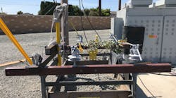
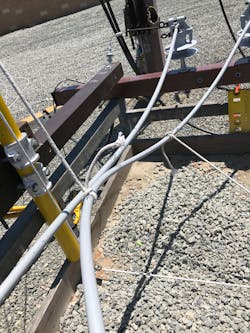
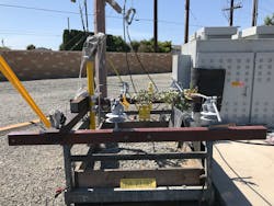
During an empirical test, various objects were positioned to connect two phases of covered conductor while energized at 12 kV for 5 minutes. Objects tested included vegetation (tree branches, tree limbs and palm fronds), wildlife, metallic balloons and conductors contacting one another. For the duration of the test, two current transformers monitored the leakage current on the covered conductors.
The empirical test found all objects yielded current magnitudes well below 1 mA. In turn, energy values generated by the contact was significantly less than 1 W. No arcing was observed during the test and no notable temperature increase was observed through infrared snapshots. Post-test analysis of the covering displayed no visible damage through any layer of the conductor’s insulation. Overall, the test validated the ability of covered conductor to prevent contact-from-object faults and their associated ignition risk.
Rollout At SCE
As part of its overall wildfire mitigation plan, SCE established the Wildfire Covered Conductor Program (WCCP) to reconductor existing bare wire with covered conductor in HFRA. Through the WCCP, SCE forecasts the installation of approximately 6200 circuit miles (9978 circuit km) of covered conductor by the end of 2023. This will equate to approximately 60% of overhead conductor circuit miles in SCE’s HFRA.
The WCCP will involve more than the replacement of bare wire with covered conductor. Reconductor work will include the installation of wildlife protection on various equipment and hardware, such as dead-ends, connectors, terminations, equipment bushings, fuses, arresters and splices, to establish an all-covered system. Simultaneously, SCE will complete numerous grid-hardening improvements. For instance, the utility will install composite crossarms and fire-resistant poles when pole upgrades are required.
With the increased weight and diameter associated with covered conductor, SCE forecasted that approximately one quarter of poles will be replaced to comply with California General Order mandated minimum safety factors. This forecast was based on system-wide analysis, and actual replacement rate will be determine as distribution lines are designed.
Most covered conductor installations use the traditional crossarm configuration, similar to existing installations of bare wire. However, SCE currently is evaluating spacer cable technology, in which covered conductor is attached to spacer hardware supported by a high-strength messenger. SCE anticipates the use of spacer cable for select situations, particularly in heavily forested areas.
Real-World Success
SCE has installed more than 1000 circuit miles (1609 km) of covered conductor since mid-2018. Subsequently, the utility has experienced real-world success with covered conductor preventing incidental contact faults.
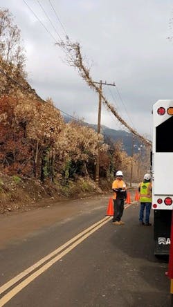
In one instance, a eucalyptus tree fell onto energized covered conductor installed in Malibu, California, U.S. The tree laid across all three phases for two hours. During this time, no fault or circuit interruption was experienced, with the covered conductor preventing a possible phase-to-phase or phase-to-ground fault. The absence of fault energy prevented any potential ignition.
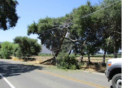
In another event, a vehicle hit a pole with covered conductor in Ojai, California. The pole broke and caused the wires to make extended contact with adjacent trees. Like the previous case, no fault or circuit interruption was experienced and, therefore, potential ignition was prevented.
With these two experiences and more, covered conductor has demonstrated its viability as a wildfire mitigation solution.
Acknowledgements
The author gratefully acknowledges Elyse Pham, Eric Hutchinson, Jesse Rorabaugh, Jim Palma and Michael Harrington for their contributions to SCE’s covered conductor testing. The author also would like to acknowledge Hunly Chy and Thuan Tran for their contributions to SCE’s overall covered conductor program.
Arianne Luy ([email protected]) is an engineer for the linear asset engineering team at Southern California Edison (SCE). She is responsible for distribution overhead conductors and underground cable accessories and has been actively involved with SCE’s wildfire mitigation initiatives regarding covered conductors. She received a BSEE degree from the University of California, Los Angeles.
